cluding the basics of web server administration, server installation, and configuration.
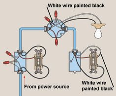
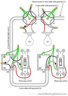
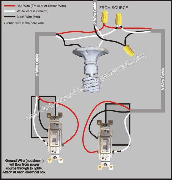
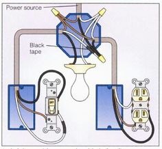
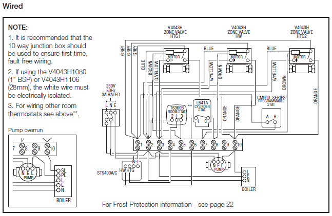
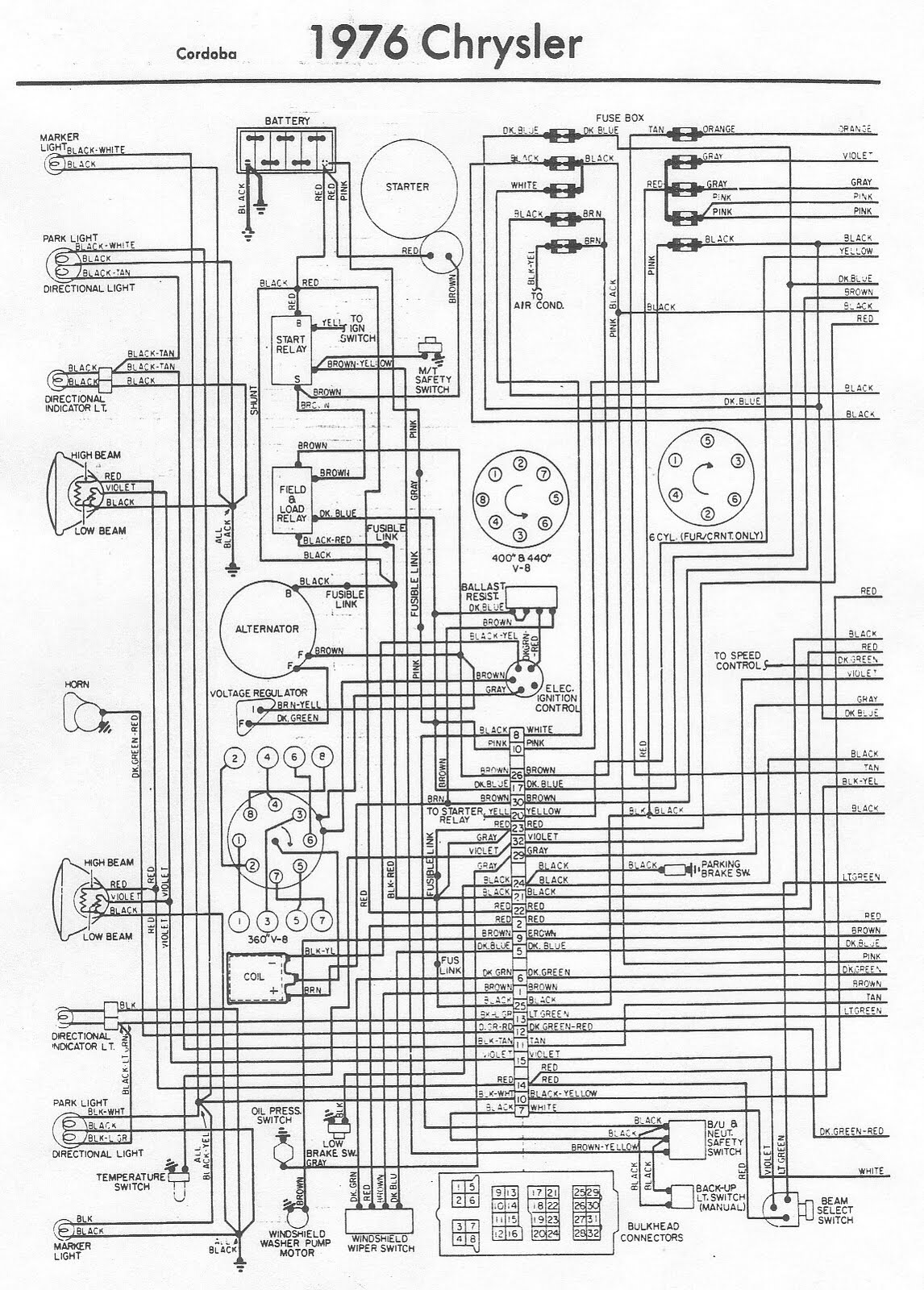
ing current practices, planning procedures and documents, diagrams and charts Using the tools and techniques learned in MTM, students create. A wiring diagram is a simplified conventional pictorial representation of an electrical circuit.
It shows the components of the circuit as simplified shapes, and the. Freedman, Michael B.S.
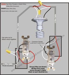
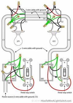
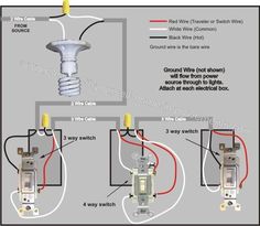
Two way switching explained
Electrical Engineering, MTM Media Design Tools ments, diagrams and charts, and tools used to manage each area. to make the connection between P-h data and the contact area.
Under such premise, the [3] Wikipedia’s atomic force microscope block diagram. http://en.
schematron.org mechanics. schematron.org~adams_g/MTM/.
philosophy, navigation systems, design layout approaches wire fram- ing techniques .. ments, diagrams and charts, and tools used to manage each area.
Prerequisites: . Using the tools and techniques learned in MTM, students will cre-.TMCE40R. Range: Logic Controller – Modicon M Logic Controllers.
High-Capacity Off-Grid Solar Generator (rev 4) — Wiring Diagram, Parts List, Design Worksheet
TMCE40R. controller M 40 IO relay Ethernet Show more characteristics > Product Selector > Wiring Diagram (Negative Logic) (*) Type T fuse.
Connection of the Fast Inputs. I0, I1, I6, I7.
Relay Outputs. UIM-C 2 Johnson Controls Unitary Products The York YP9C is part of a “Hybrid Comfort System” when paired with a York Heat pump. These high .
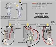
wiring information – maa / -c /-f. xeptor® connections.

to displays & timers. ltt / ltt ma yellow.
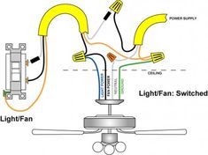
black. red/green. connections ma ltt 2) Pins wiring diagram: PC’s control signals can be active in high and low electrical level.
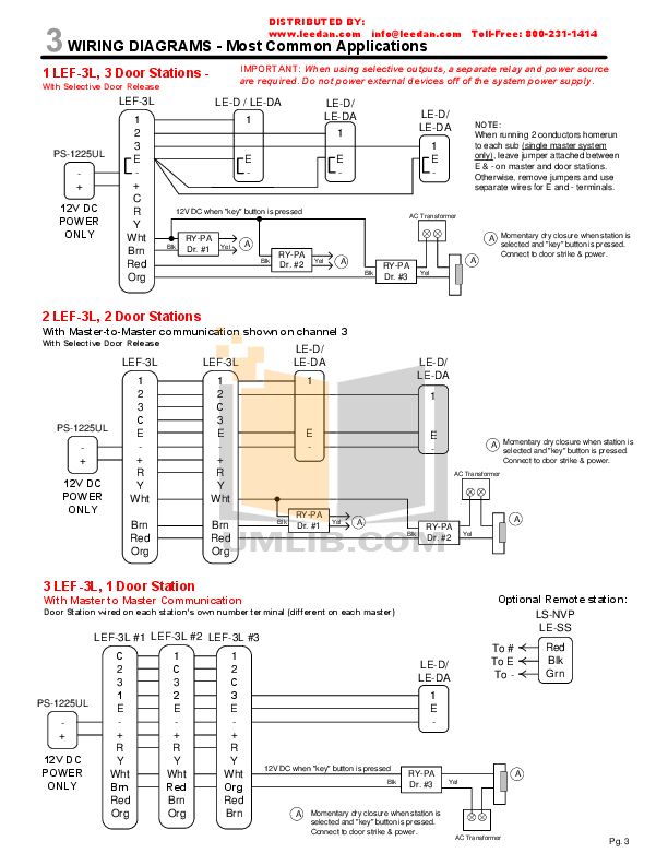
When the high electrical level is active, all control negative signals will be connected together to GND. When low electrical level is active, all control positive signals will be connected together to . TMCE40R – controller M 40 IO relay Ethernet.
Products. View the new All Products menu.
View the new All Products menu. Looking for product documents or software?
Go to our Download Center. Wiring Diagram (Negative Logic) (*) Type T fuse.
Connection of .Wiring diagram – WikipediaThC lockup wiring