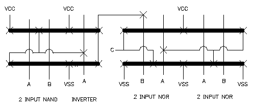
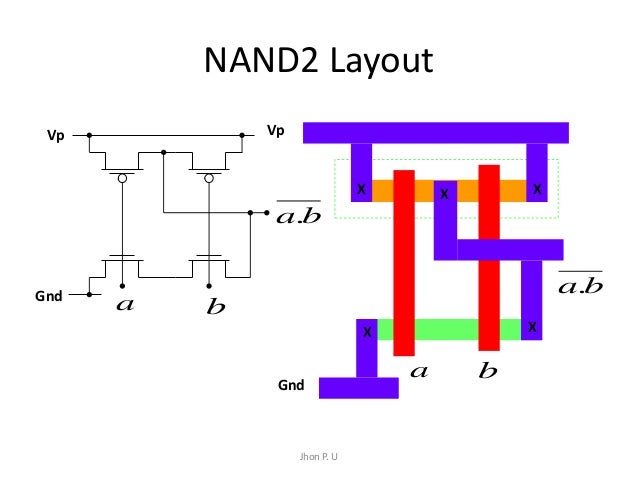
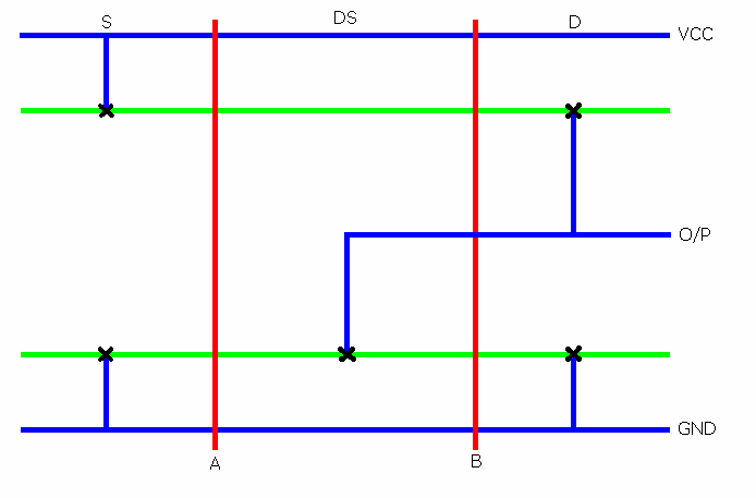
hi, can any body please draw me a layout/stick diagram for 2 input NAND gate with 2 fingers? thanks in advance.
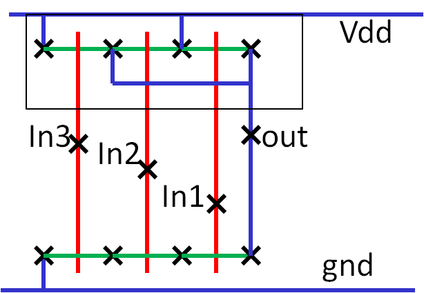
Top-down and Bottom-up Design Approach Stick Diagrams Stick Diagrams for nMOS 4 – 38 Two Inputs nMOS NAND Gate 1) Draw the transistor level schematic (CMOS) and stick diagram for the following : a) 3 input NAND gate. b) 3 input NOR gate c) A+B(C+D+E) d) AB + CD +EF.
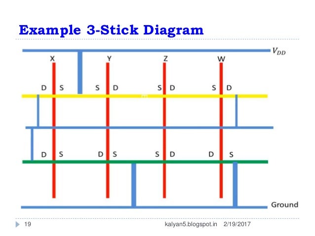
Figure shows the stick diagram of a CMOS inverter gate. In this case A CMOS NAND gate requires two series pull-down NMOS transistors con- nected to. CMOS-Layout-Design.
Layout of Logic gates: Three Input NAND Gate: Figure below shows, the schematic, stick diagram and layout of three input NAND gate.The corresponding stick diagram of NOR3 gate is shown below. Stick Diagram of NOR3. Inverter’s stick diagram is shown at the end.

the arrows represent the Euler paths. It is very important that in PDN and PUN transistors are being accessed in the same order. Again.
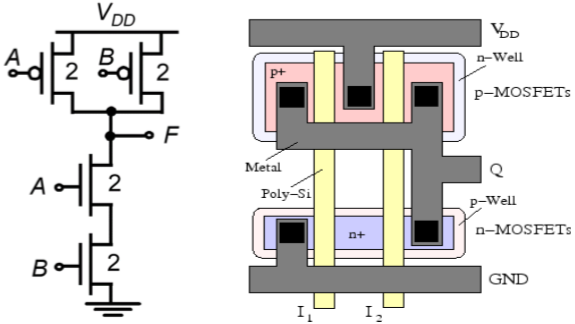
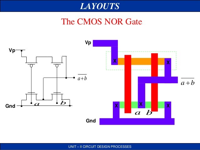
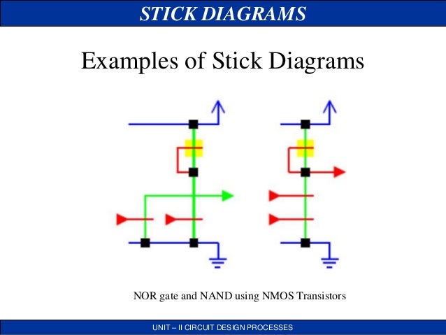
in the schematic/5(1). STICK DIAGRAMS UNIT – II CIRCUIT DESIGN PROCESSES Examples of Stick Diagrams STICK DIAGRAMS UNIT – II CIRCUIT DESIGN PROCESSES Examples of Stick Diagrams STICK DIAGRAMS UNIT – II CIRCUIT DESIGN PROCESSES Examples of Stick Diagrams NOR gate and NAND using NMOS Transistors Aug 02, · 2 Input Cmos Nor Gate Stick Diagram solution to NOR gates only.
Problem 3. Determine Determine the output transitions tHL if a two-input minimum-sized CMOS.
NAND gate is driving a Page 2. Problem 8.
A stick diagram has been put together for a 3-input CMOS NAND gate. MIPS Processor Example.
CMOS VLSI Design. CMOS VLSI Design 4th Ed.
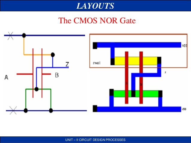
2 Activity 2. STICK DIAGRAMS UNIT – II CIRCUIT DESIGN PROCESSES Examples of Stick Diagrams STICK DIAGRAMS UNIT – II CIRCUIT DESIGN PROCESSES Examples of Stick Diagrams STICK DIAGRAMS UNIT – II CIRCUIT DESIGN PROCESSES Examples of Stick Diagrams NOR gate and NAND using NMOS Transistors Example of the layout (stick diagram) of a 3-by-4NAND ROM array is shown in Figure GND R3 R2 R1 C1 C2 C3 C4 1 0 0 1 1 1 0 0 1 GND VDD 1 1 1 Figure A stick diagram of a 3-by-4 NAND ROM array In the layout, similarly to the NOR ROM, the bit lines (columns) are implemented in metal 1 and the word lines (rows) connecting the gates.layout/stick diagram for 2 input NAND gate with 2 fingersNor Gate Layout Amazing 3 Input Nand Gate Stick Diagram 3 Input Truth Table – layout design
