To optimize your engine’s performance, ensuring accurate connections between the ignition control unit and its components is critical. A precise setup guarantees that all parts work harmoniously, leading to improved efficiency and reliability. Begin by identifying the correct terminals on the control unit, ensuring they match the wiring specifications for your vehicle or system type.
First, check the primary power and ground connections. The ground wire should be securely attached to the engine block or chassis to minimize electrical interference. A solid power connection is crucial for maintaining consistent operation and preventing voltage drops that could lead to performance issues.
Next, focus on connecting the triggering signal wires. These wires transmit vital information to the control unit, triggering the necessary adjustments for ignition timing. Misconnections here can result in erratic performance, poor fuel efficiency, or even engine misfires. It’s essential to follow the manufacturer’s color code and guidelines for these signals to avoid confusion.
For maximum efficiency, double-check all connections after installation. Test each component with a multimeter to ensure there’s no resistance in the connections. This step is essential for preventing future issues and ensuring optimal engine response.
Lastly, always refer to your system’s specific manual for any unique instructions. While there are general guidelines for installation, each performance unit may have slight variations in wiring or configuration, so attention to detail is key.
Wiring Setup for the MSD Control Module

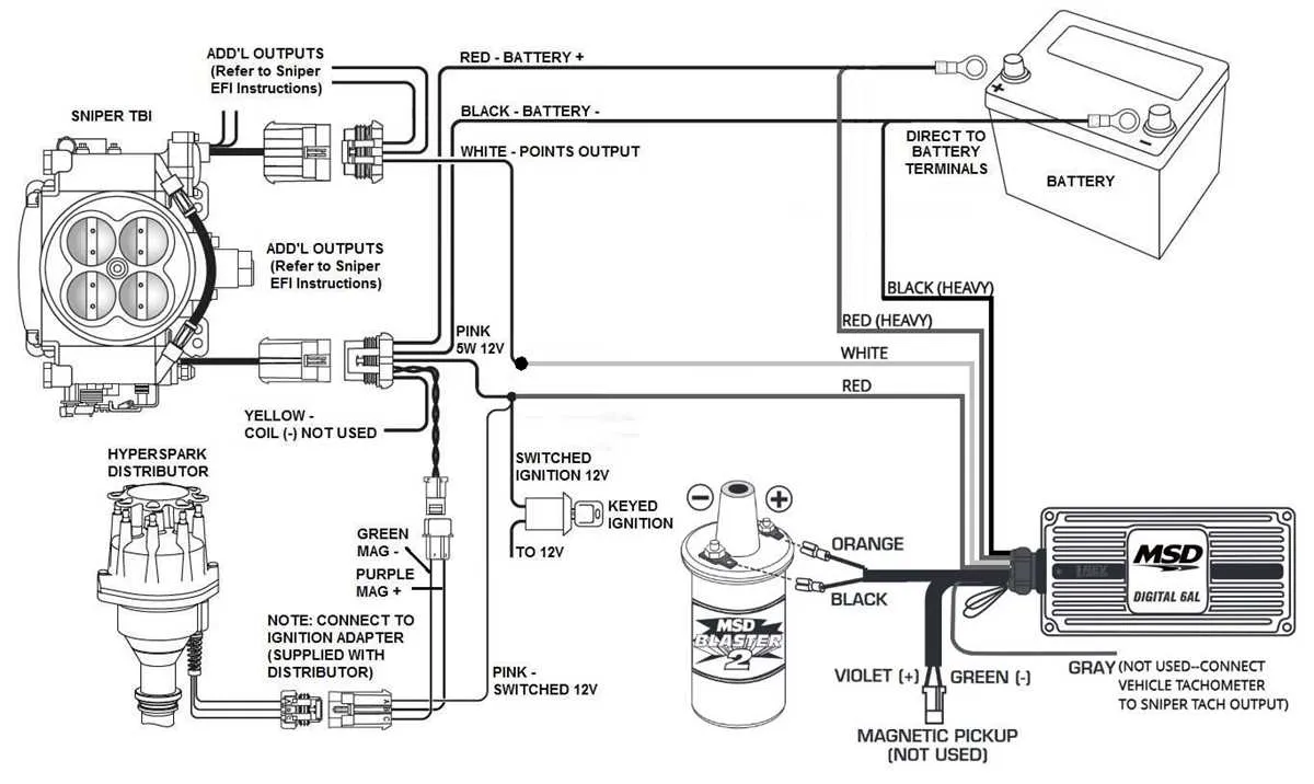
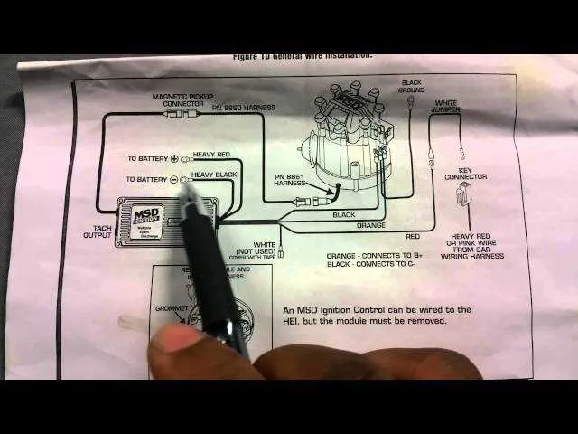
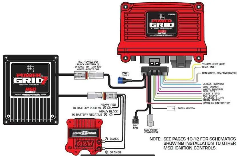
To ensure proper functionality of the MSD control module, begin by connecting the power wire (typically red) to the battery positive terminal or the ignition switch. This wire powers the unit when the engine is running.
The ground wire (usually black) should be securely attached to the chassis or engine block. Make sure the connection is clean and free of rust to prevent voltage fluctuations that could interfere with performance.
For the signal input, use the tachometer lead (often green). This wire connects to the distributor or the crankshaft sensor depending on your setup, sending the timing signal to the control unit.
Connect the coil trigger wire (usually purple) to the coil negative terminal. This wire controls when the spark occurs and ensures that the ignition system fires at the correct time.
Some systems include a third wire (typically white) to activate the timing retard feature. If applicable, this wire can be connected to a switch or the vehicle’s ECU for advanced timing adjustments based on boost or nitrous input.
Finally, ensure all connections are tightly secured and insulated, and check the system’s voltage with a multimeter before attempting to start the engine. Miswiring can cause erratic behavior or prevent the system from activating entirely.
Step-by-Step Guide to Connecting the MSD Ignition System to Your Vehicle
1. Start by disconnecting the vehicle’s battery to prevent accidental shorts during the installation process.
2. Locate a suitable mounting location for the system, ensuring it’s away from heat sources and direct exposure to moisture.
3. Mount the unit securely using the provided brackets or custom mounts. Ensure the mounting surface is clean and free from debris.
4. Connect the primary 12V power wire to a constant 12V source. This will provide power to the unit when the vehicle is on.
5. Attach the trigger wire to the distributor’s points or signal generator. This wire will be responsible for receiving the signal that triggers the unit’s operation.
6. Connect the high-voltage output terminal to the coil’s positive terminal, ensuring the proper connection of the spark-producing circuit.
7. The ground wire should be securely attached to the vehicle’s chassis or an unpainted metal surface for a solid ground connection.
8. Attach the tachometer wire to the tach input if you plan to monitor engine RPM, following the manufacturer’s instructions for your specific tach setup.
9. Once all connections are made, double-check each one for proper tightness and contact to avoid any issues during operation.
10. Reconnect the vehicle’s battery and power up the system. Test the setup by turning the engine over to verify that the system is functioning properly.
11. Finally, perform a road test to ensure optimal performance under normal driving conditions. Make adjustments if necessary.
Identifying and Troubleshooting Common Wiring Issues in MSD Ignition Systems
When working with high-performance ignition systems, poor electrical connections or faulty setups can cause significant problems. Here are practical tips for identifying and fixing common issues:
- Loose or Corroded Connections: Check all terminal connections for corrosion or looseness, especially at ground points and the power supply. A poor connection can lead to intermittent power loss or weak spark delivery.
- Incorrect Grounding: Ensure that the system is properly grounded to avoid erratic behavior. A weak ground can cause misfires, poor acceleration, or even failure to start. Use a dedicated ground wire from the unit to the battery’s negative terminal.
- Inadequate Power Supply: Make sure the power leads are capable of handling the necessary current load. Thin or damaged wires can cause voltage drops and erratic system behavior. Use the correct gauge wire recommended by the manufacturer for both power and signal lines.
- Short Circuits: Inspect all wires for signs of abrasion or exposure that might lead to short circuits. Even a small breach in the insulation can cause a short, disrupting signal flow and causing system malfunction.
- Signal Interference: Interference from other electrical components can impact system performance. Check for unwanted interference, particularly from high-output devices such as fuel injectors or aftermarket sensors. Routing wires away from high-voltage sources can reduce this risk.
- Improper Sensor Connections: Verify all sensor connections are correctly installed and functional. Faulty or disconnected sensors will prevent the system from adjusting spark timing, leading to poor engine performance.
Regular maintenance checks and the use of high-quality connectors can prevent most of these issues. Always follow the manufacturer’s installation instructions to avoid common pitfalls.
Optimizing Performance with Proper MSD Ignition Box Wiring Techniques

Ensure a clean and solid connection between the control unit and power sources to maximize signal strength and reduce voltage drop. Use high-quality, short leads for power supply and ground connections. The shorter the wire length, the less resistance and interference will affect performance.
Grounding is critical–use a dedicated ground point on the chassis, preferably close to the control unit, to minimize noise and improve signal integrity. Avoid sharing the same ground with other components, as this can introduce unwanted electrical noise and cause erratic behavior.
For signal distribution, ensure the use of shielded wires. This will prevent electromagnetic interference (EMI) that could disrupt proper operation, especially in high-performance applications. Use ferrite beads or other noise-filtering components on wires where necessary, particularly in the lead that runs to the coil or distributor.
Always verify that all connectors are securely fastened, and use dielectric grease to prevent corrosion. A loose connection, even slightly, can lead to signal degradation, leading to misfires or irregular timing.
It’s also crucial to route wires away from heat sources such as exhaust manifolds or turbochargers. Excessive heat can degrade wire insulation, leading to short circuits or signal losses. Insulate wires in high-temperature areas to ensure they remain operational under extreme conditions.
When routing wires, keep them away from sources of electrical noise like alternators, relays, or ignition coils. If necessary, use a braided ground strap between components to ensure a solid path for electrical flow and prevent power loss.
Lastly, always double-check the voltage at the control unit’s power input. Low or fluctuating voltage can lead to erratic performance and even component failure. Ensure your charging system is in optimal condition to provide consistent voltage to the control unit at all times.