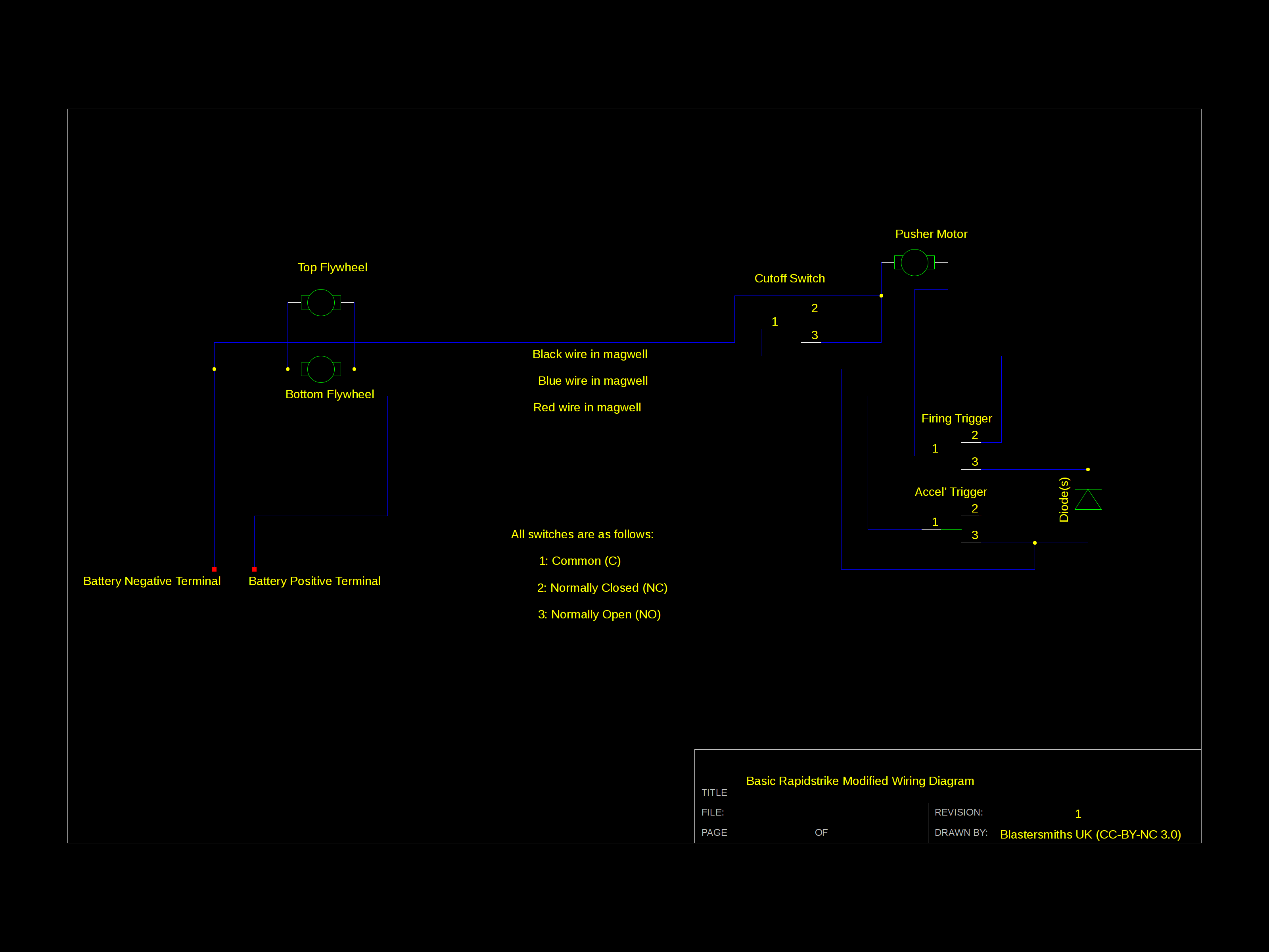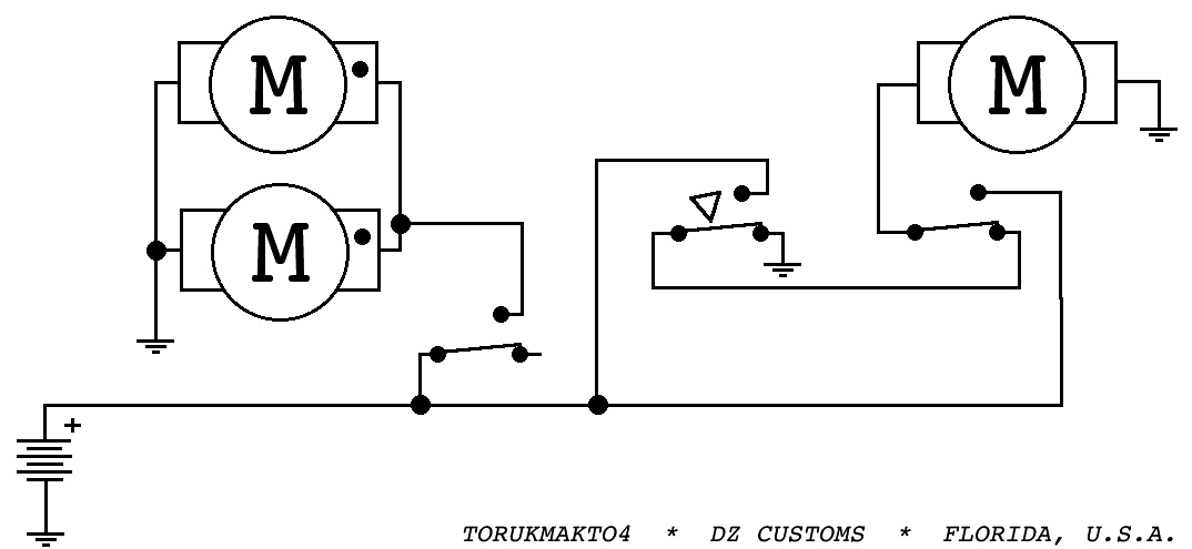
Looking to see if anyone has a diagram showing the best positions for a mosfet(s ), resistor(s), and diode(s).
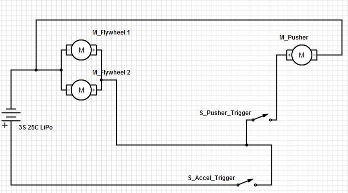
I would like to use a setup like. I can’t seem to find where my problem is with the wiring.
The motor The details and diagrams are a bit too much for me to understand. Without.
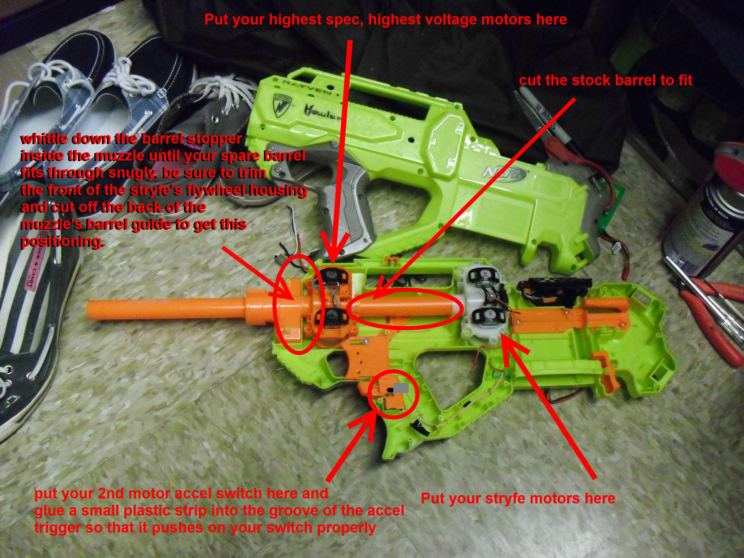
Finally the vaunted 3-switch Rapidstrike Wiring Diagram. I hope this helps. Flywheel Assembly: schematron.org Email Address.
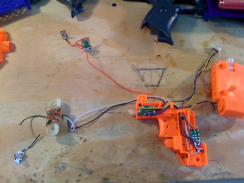
The primary goal of this mod was to rewire the Rapidstrike so that it could use a battery pack, I don’t have any final shots of the wiring, but it’s just as well. A Good Blaster at Your Side: Modifying the Nerf Han Solo Blaster.
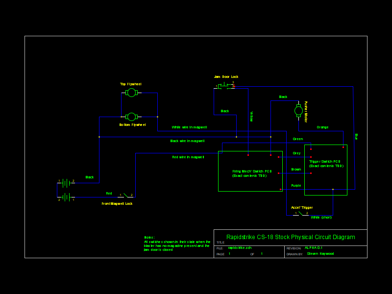
I looked at and researched on a lot of the wiring diagrams for rapidstrike and I don’t really understand the wiring for the third switch hence my.Rapidstrike CS Circuit Schematics. NOTE: These are preserved here for posterity, there are a couple of errors that are to be corrected in a later post.:) The suggested rewire needs electrical braking adding and the motor stack on the flywheels needs completing.
The benefit of wiring the NO terminal of the switch to the positive terminal of the battery is that it allows you to easily implement motor braking in the future by simply adding a wire between the NC terminal of the switch and the negative terminal of the battery (if you try to do that with C and NO connections reversed you’ll just short the. Put them in the Rapidstrike and Stryfe, configured the same so the magazines detect the same in either blaster.
I also swapped out the switch i was using for the trigger counter in the Rapidstrike. It was detecting the movement of the pusher arm but i found if the blaster was held at an angle, the lever on the switch would jam against the. A complete wiring harness and switch upgrade kit including Blastersmiths UK’s own switch plate upgrade, all the 18AWG wire you’ll ever need and the switches and battery connectors to go with it.
Re: Rapidstrike CS Circuit Schematics. Submitted from Herbert West: Hi Nerf Armourer, I’m glad to see that someone is finally putting the RS’ circuitry online, but there are a few problems with both diagrams! The circuit diagram that you’re showing for the stock RS is missing the innermost PCB that sits on the flywheel cage.The Dart Zone: Tech: Rapidstrike Control Circuits Part 1Re: Rapidstrike CS Circuit Schematics – Diaries of a Nerf Armourer
