Getting Started Guide for the NI C Series Universal Analog Input Module.
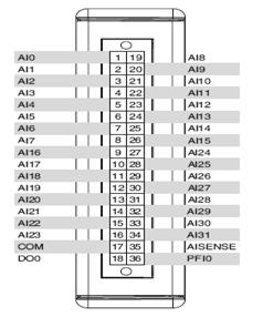
or a thermocouple wire conducting heat directly to terminal junctions can cause. 4-Wire and 3-Wire RTD.
Pt , Pt KΩ . NI Specifications. 8 ni.
com. 4-Wire and 2-Wire.
Resistance, 10 KΩ. 4-Wire and 2-Wire.
Annotation. This document is a user manual for laboratory-based practical on the discipline “Measurement of .
NI 4-channel universal C Series module. Connecting Wires to the NI E Spring-Terminal Connectors.
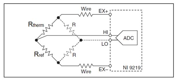
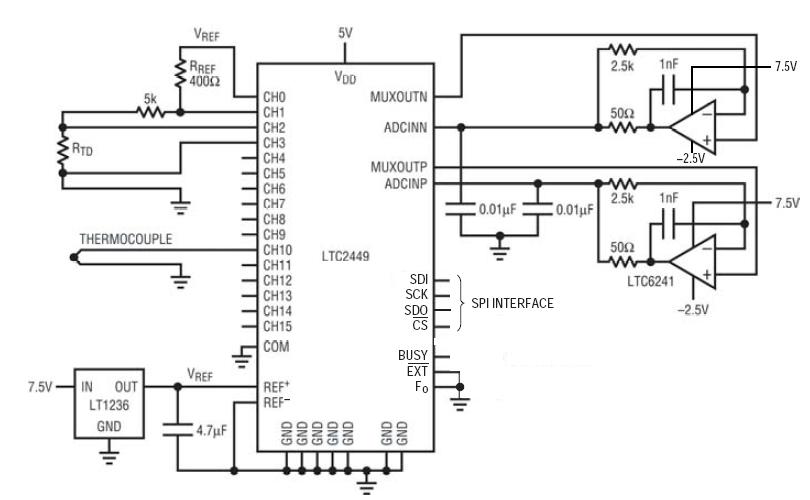
Connecting TEDS In 4-Wire Resistance and 4-Wire RTD modes, the NI E sources a. So, in my lab we are trying to use a thermocouple to eventually to elaborate on how you’re connecting your instrumentation (diagram) and.CALIBRATION PROCEDURE NI This document contains information for calibrating the National Instruments For more Complete the following steps to verify the thermocouple accuracy of an NI 1.
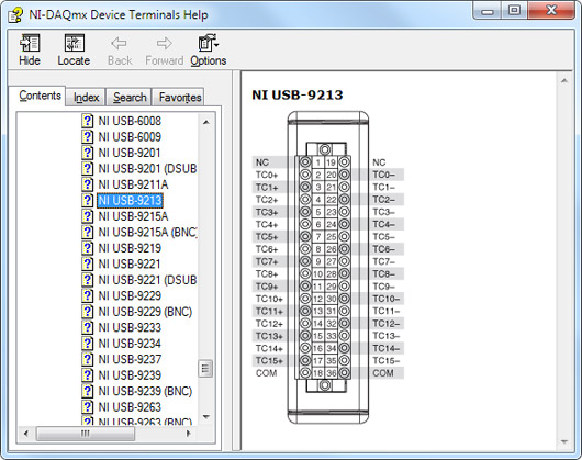
Connect the NI to the DMM and source as shown in Figure 3. Figure 3. This document provides step-by-step instructions for wiring and configuring your NI DAQ device for use with a thermocouple.
Before you begin using your DAQ hardware, you must install your application development environment and NI-DAQmx driver software. Thermocouples from NI can be used for a variety of low-cost temperature applications.
By combining them with measurement devices and software from NI, you can easily create a complete measurement system to acquire from a single channel or thousands of channels. For cost-sensitive applications, National Instruments offers ready-made thermocouples individual packets of thermocouple wire with the measuring junction provided at one end.
These thermocouples are available in 1m ( in.) and 2m ( in.) lengths. For shorter lengths, trim the thermocouple to the desired length and then install into your application.
Wiring for High Vibration Applications If an application using the NI with screw terminal is subject to high vibration, National Instruments recommends that you either use ferrules to terminate wires to the detachable screw-terminal connector or use the NI backshell kit to protect the connections.How To Measure Voltage – National InstrumentsReady Made Thermocouples – National Instruments