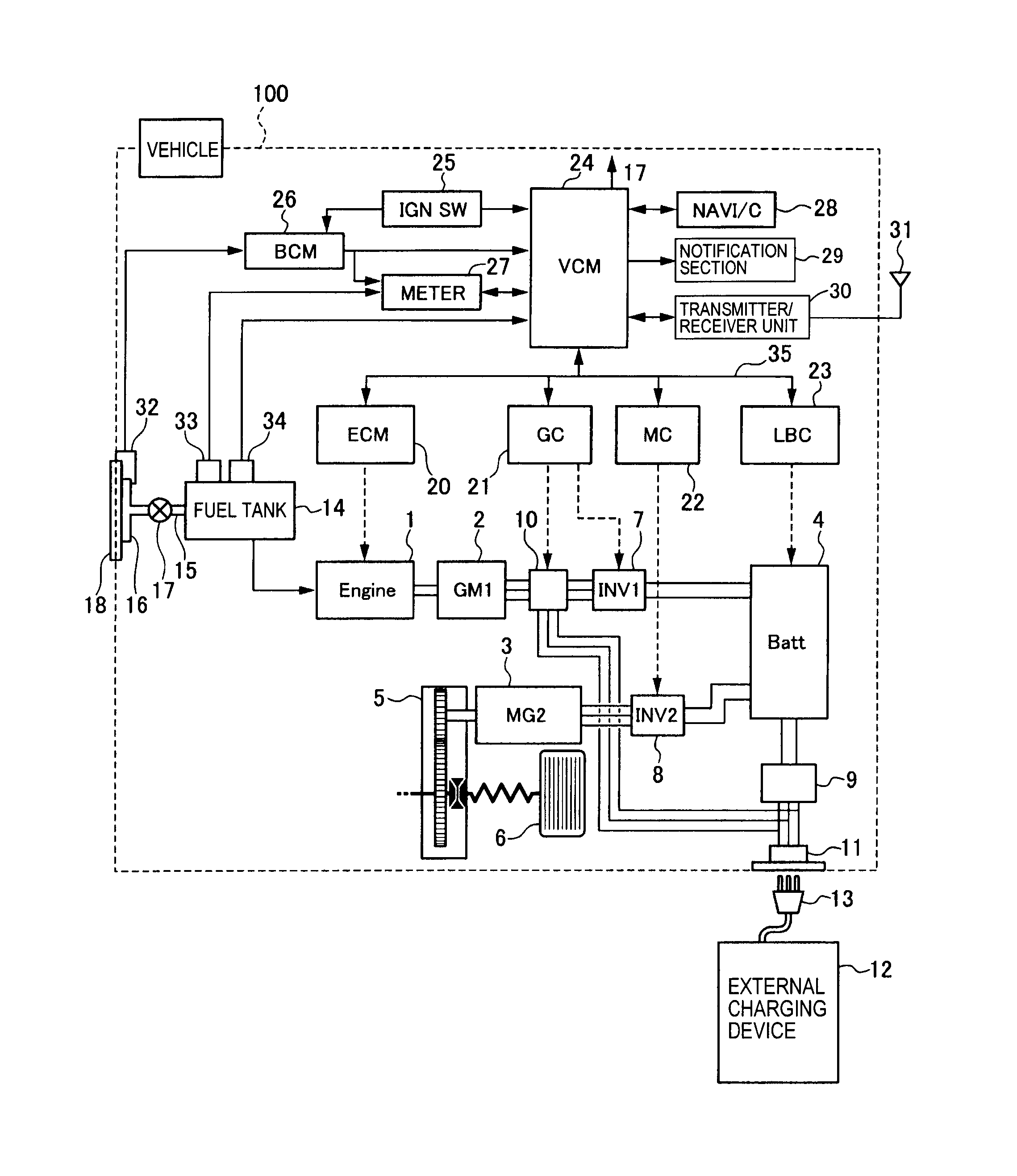
three-wire strain gauges to one NI RJ50/Terminal connector that will then connect.
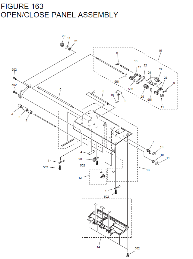
I would recommend you look at the connection diagram that is how to connect the strain gage wires to the pinout of the As shown below, there is a diagram in the NI / Quarter Bridge resistor, which the NI / internally hard wires across R3. Each load cell will be wired to the NI and connected to the NI ..
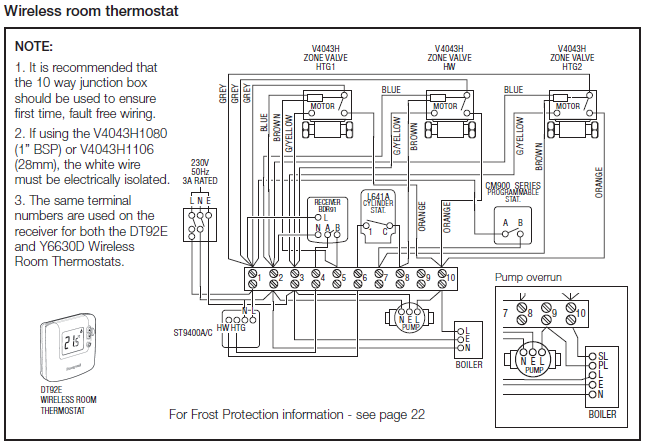
If the base becomes, warped, rusted, or unusable, the diagrams below can be used. How do I perform shunt calibration with NI? Note: If your strain gage only has 4 wires, then you do not need to connect the two wires for.
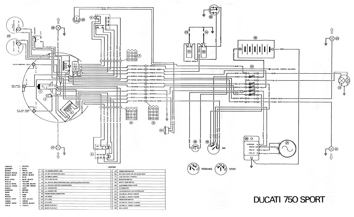
the wires connecting the excitation voltage to the bridge is a source of gain error. Figure 3 shows a diagram of how the NI uses remote sensing.

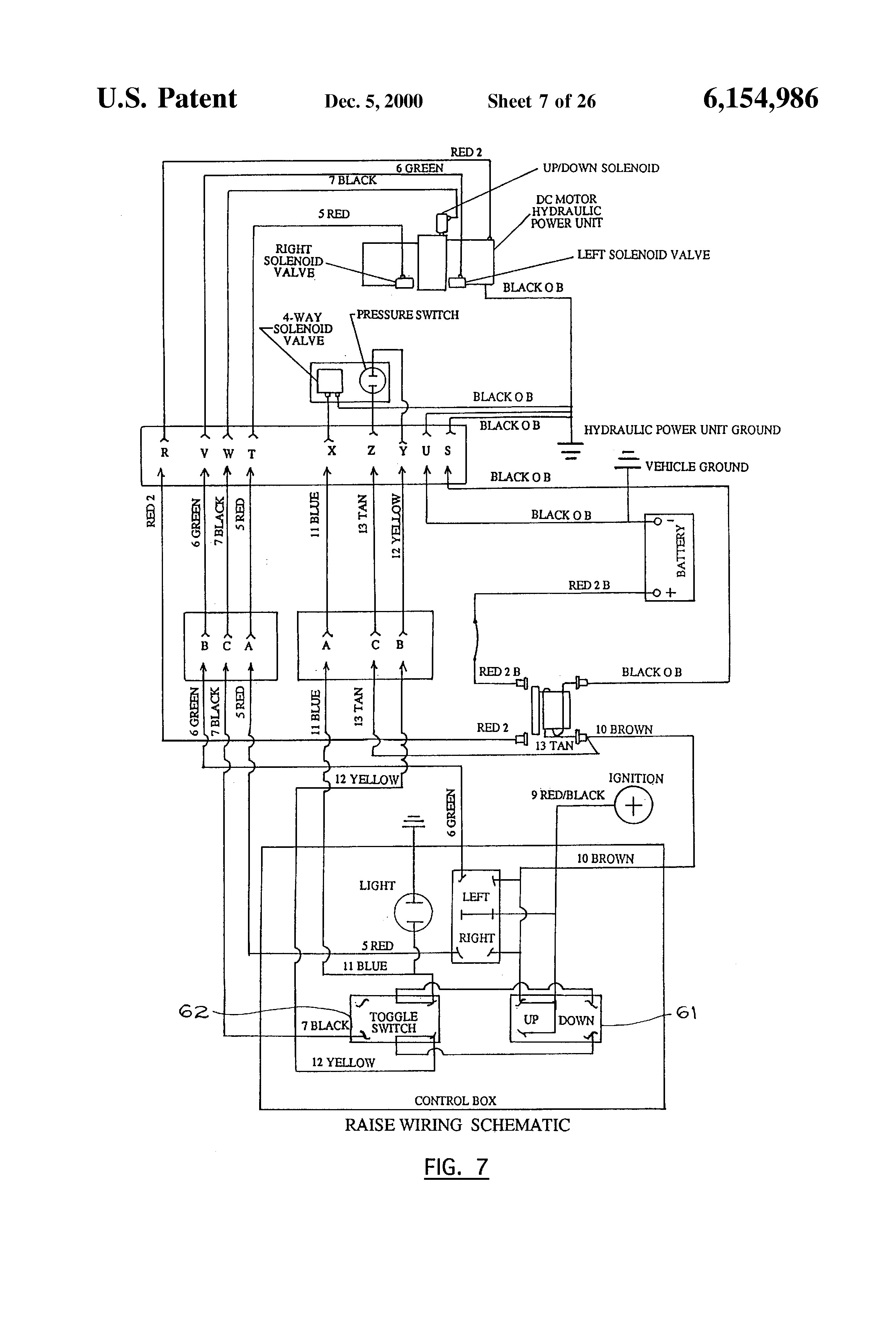
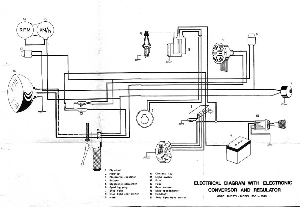
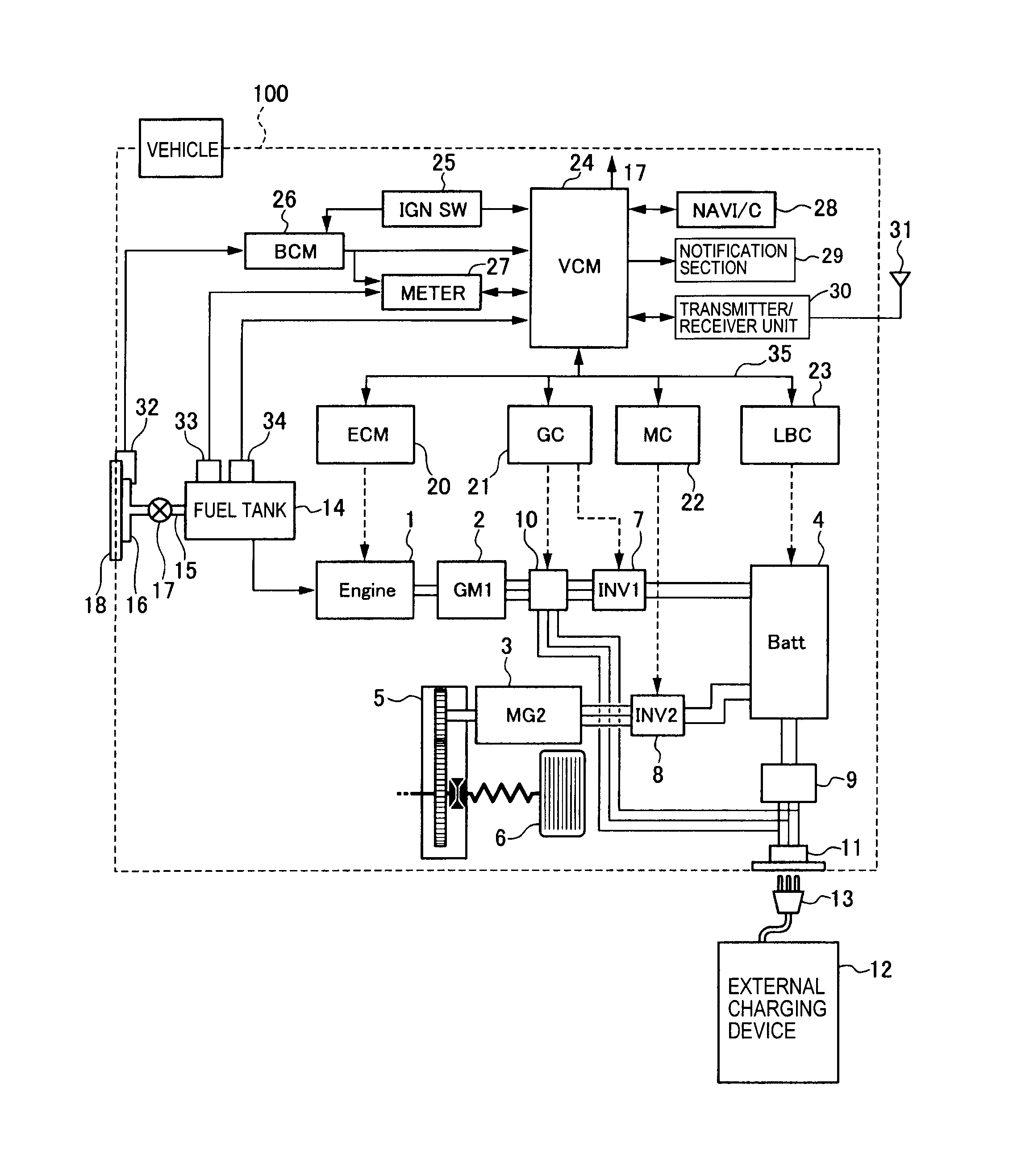
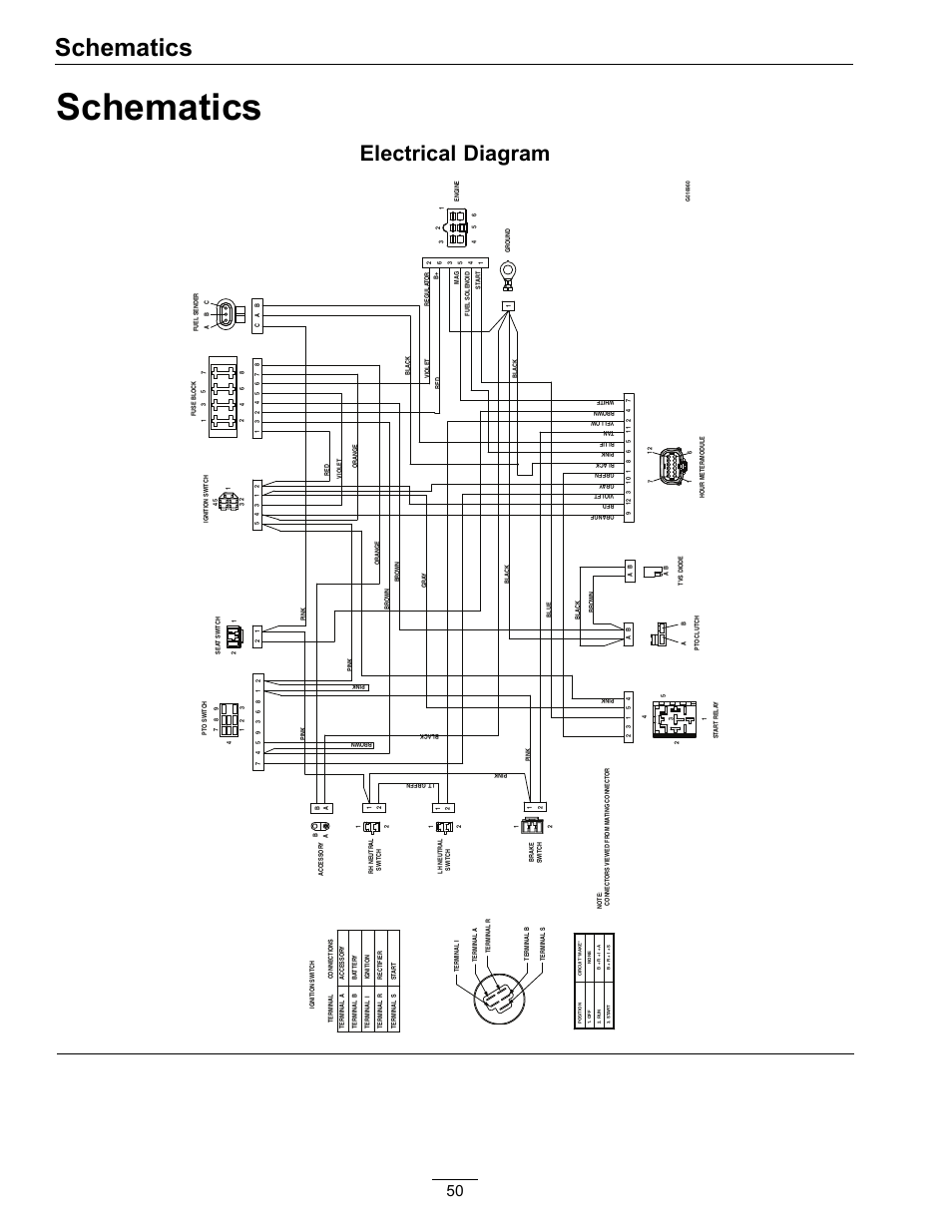
Figure 3.A wiring diagram is a simple visual representation of the physical connections and physical layout of an electrical system or circuit. It shows how the electrical wires are interconnected and can also show where fixtures and components may be connected to the system. Jan 17, · Learn to navigate this system’s wiring circuitry and diagram using current flow analysis, relay and module operation and neutral-switch actuation, such as circuit completion.
See how the anti. USER GUIDE AND SPECIFICATIONS NI USB 4-Channel, Bit Half/Full-Bridge Analog Input Device This user guide describes how to use the National Instruments USB and lists the device specifications. The NI USB provides a USB interface for four channels of .
NI RJ to Screw-Terminal Accessory This user guide describes the features of the National Instruments RJ to Screw-Terminal Accessory. You can use the NI to provide for a diagram of the RJ and screw-terminal connectors on the NI Refer to the device manual for information about device pin assignments.
DBPin And Wiring Connecting To A Torque Sensor Using A Ni 8p. I am new to labview and trying to connect a Futek torque sensor to a NI I am not sure of the wiring of torque sensor to the pin connections of the NI , I would like to be able to measure torque as well as angular position.
The wiring diagram in Lab 2.Configuring the NI or NI with the NI – National InstrumentsNI – National Instruments