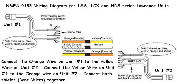
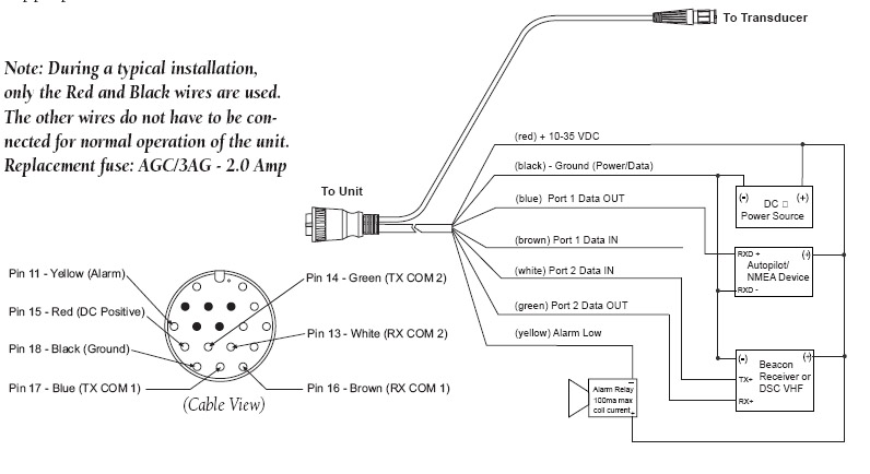
to be shown simultaneously on both an NMEA device and an NMEA NMEA connector becomes the NMEA cable. Wiring diagram.
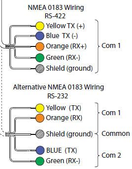
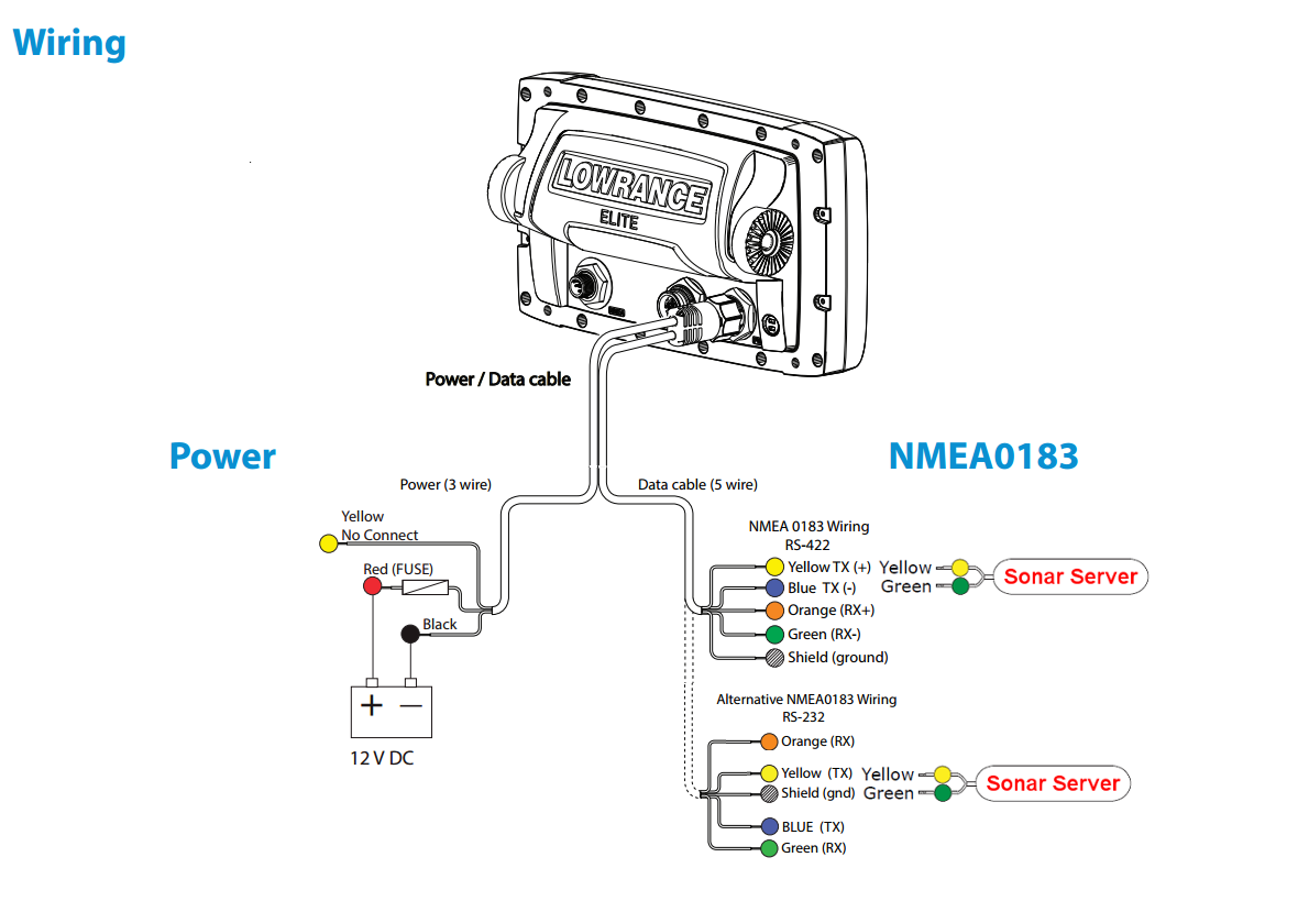
Typically NMEA wiring will adhere to the minimal 3 wire The wiring diagram to the right shows multiple devices connected together as. to be shown simultaneously on both an NMEA device and an NMEA NMEA connector becomes the NMEA cable. Wiring diagram.
THIRD PARTY NMEA GPS. WIRING DIAGRAM.
4. 5. 3.
1. 2. M12 FEMALE.

3. 5. 4.
2. 1.
M12 MALE. CONTROL PANEL (CP-S).
BACK. 1 YELLOW. 2 WHITE.
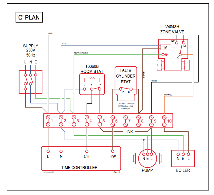
to be shown simultaneously on both an NMEA device and an NMEA NMEA connector becomes the NMEA cable. Wiring diagram.Diagram 2.
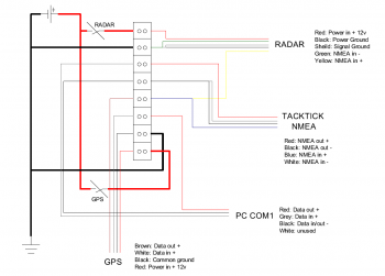
As diagram 1, but here the instruments are inter-connected in a network with a common NMEA output. Diagram 3.
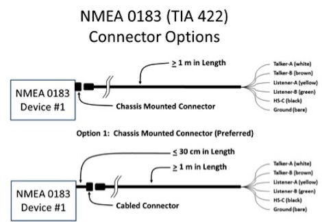
In this configuration, the multiplexer has the optional Seatalk conversion option installed. The multiplexer converts Raymarine Seatalk data to NMEA Interface diagram(s) in accordance with the examples contained herein, showing all equipment pigtails cannot all be joined at the same barrier strip location and the NMEA network wiring is extended, the Talker color code should be used for cabling Interfaces between NMEA or NMEA HS and an NMEA NMEA Offers Insurance for FL, LA, GA, NC, SC, TN, TX, VA and MD Members VHF DIY Guide for Boaters How to Choose Your Electronics.
Worldwide Boat Show Calendar. Our Industry Partners: Search NMEA Certified Products.
Official magazine of the National Marine. Before continuing, a short familarization with NMEA is in order.
NMEA is a point-to-point connection scheme that is used to interconnect navigation equipment. Any device that supports MMEA “should” be capable of communicating with other NMEA devices.
Use this NMEA cable for when you need to share numeric data on your boat.GPSMAP Series Installation Instructions – Advanced NMEA ConnectionsDiagrams for standard model Brookhouse NMEA multiplexer