BEFORE YOU BEGIN: Read these instructions completely.
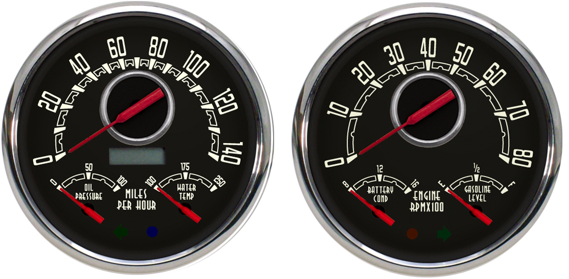
Plan out your wiring scheme ahead of time. Use the included wiring diagrams to help guide your wire .
Find Links below to NVU instructions available online Download our instruction manual here Instruction booklet for all gauge sets on the Phoenix platform. NEW VINTAGE INSTRUMENT AND GAUGE KIT.
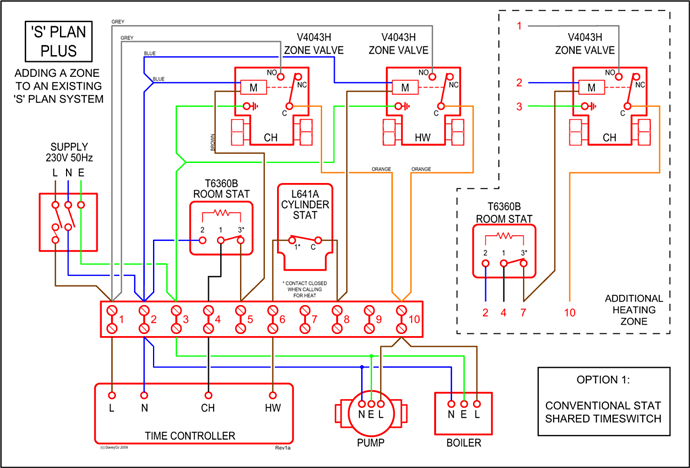
INSTALLATION Use the included wiring diagrams to help guide your wire . available at most NVU retailers.
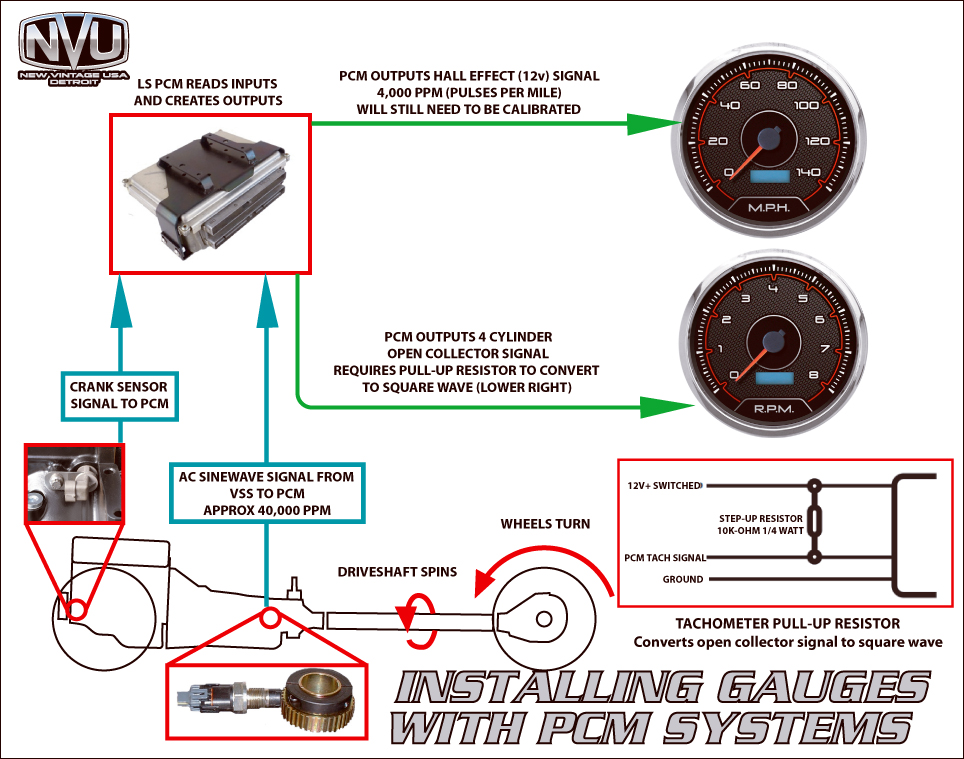
gauge, NVU air core units pass 50G shock tests where NVU stepper gauges will pass PCM output. Check your PCM wiring diagram for the proper outputs.

BEFORE YOU BEGIN: Read these instructions completely. Plan out your wiring scheme ahead of time. Use the included wiring diagrams to help guide your wire .All gauges require 4 things to be connected: Power, Ground, Lights and signal.
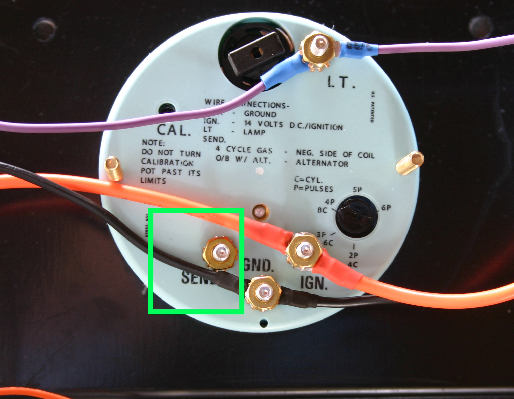
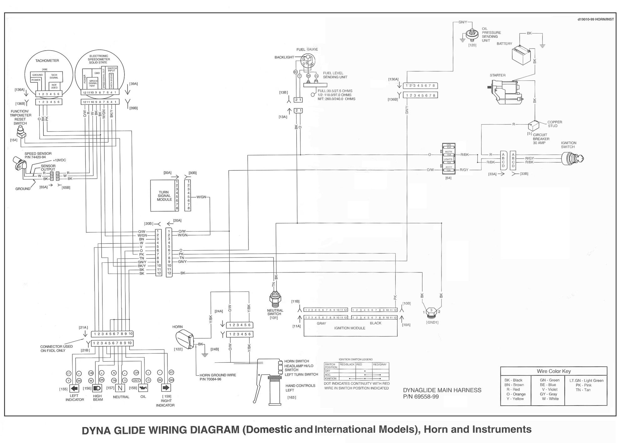
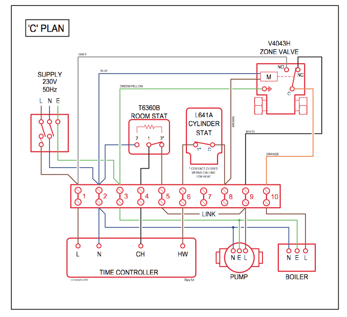
That really is it. There may be additional wiring for other features like programming button, warning outputs, etc, but let’s keep this simple as it really comes down to those 4 wires. See the image below for a basic wiring diagram.
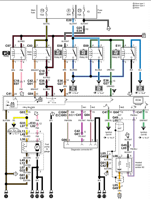
Gauge Set Installation Manuals. General Installation Manual (Gauge sets comprised of individual gauges) Download SN81SF Sky Fence Wiring Diagram. SN84 6 Gauge Wire Harness.
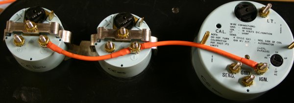
Download SN84 Installation Guide. Fuel Sender with Float Arm.
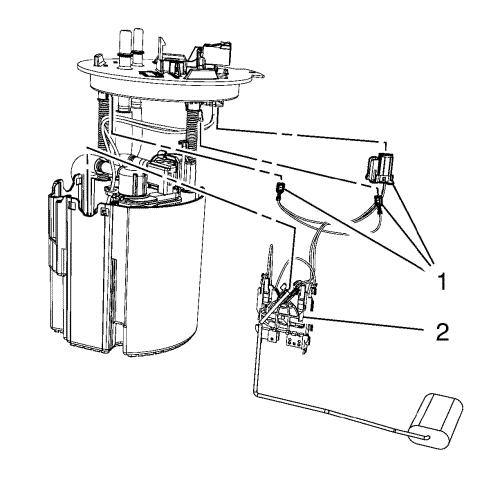
Download Fuel . Wiring the gauges: Run the power wiring from the gauges to an appropriate positive (+) on the fuse block after the battery.
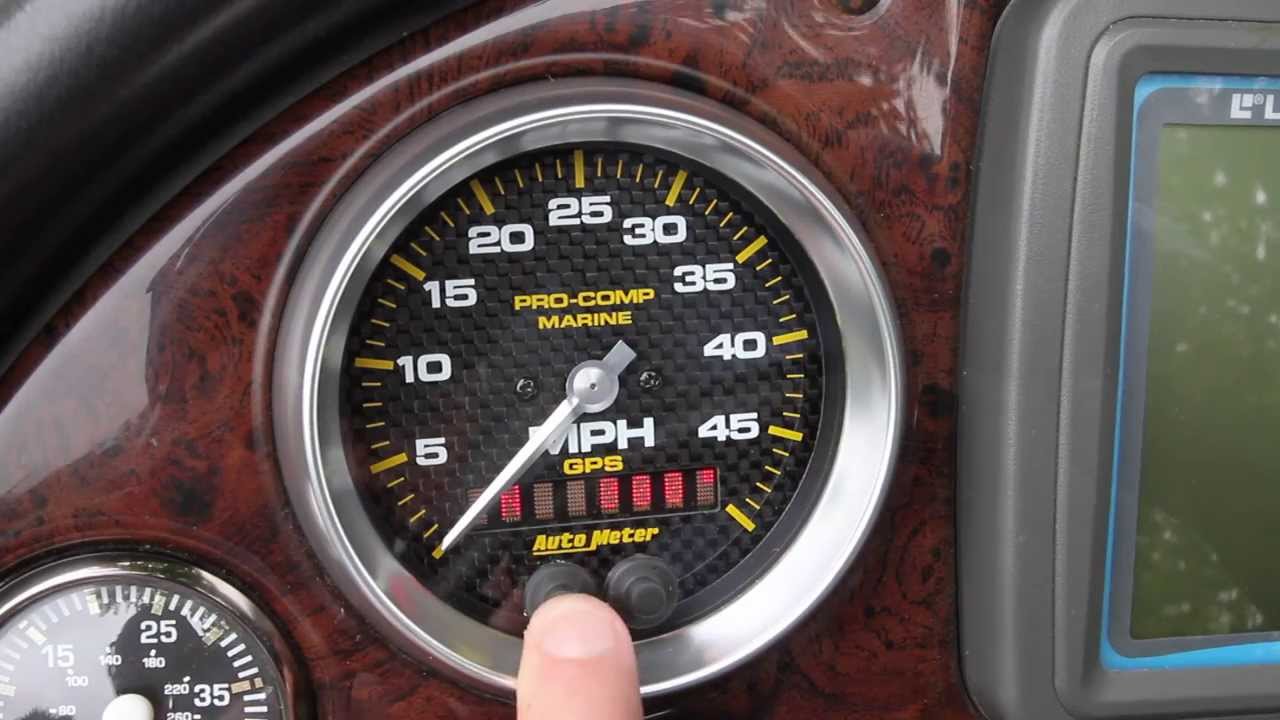
This applies to the switched 12V+ and gauge lighting Connect the ground to a good dedicated ground on the chassis Run each wire to the appropriate sender and use the proper connector for each item. , and gauges with the corresponding sender will read full or high if the sender has a bad ground.
and gauges with corresponding senders will read empty or low if the sender has a bad ground. The most common problem with a ohm gauge and a SN35 sender is the gauge reading Empty or not reading all the way to full. NOTE: Wire for gauge lights must be purchased separately.
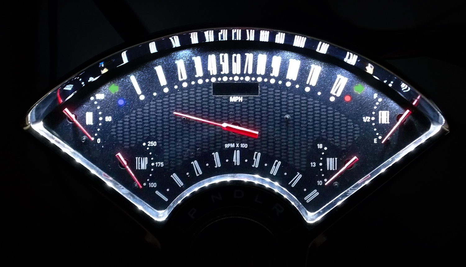
Use size AWG stranded copper wire. 2. Splice the RED or WHITE wire from the gauge light(s) into the vehicle’s lighting circuit, between the dimmer control switch and the dash lights (consult the vehi-cle’s service manual for proper wire).
3 GAUGE LIGHT INSTALLATION AND CONNECTION3.Electronic Speedometer how to and why from NVU – New Vintage USA INCTroubleshooting