When re-wiring my c Evinrude TRIM gauge last weekend, I noticed that manual and I noticed a pictorial diagram that showed the wiring. hey guys need a wiring diagram for a evinrude tilt trim unit.
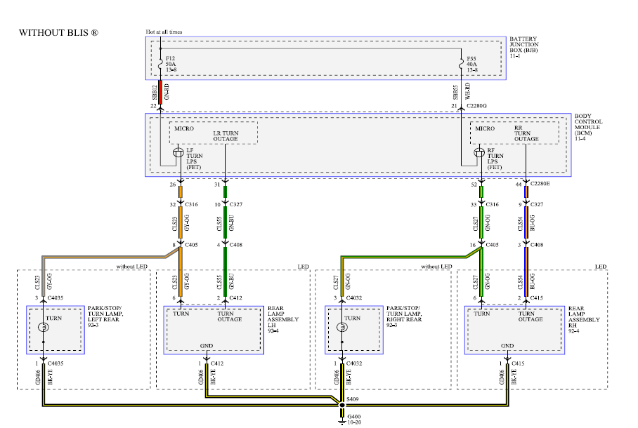
need to get it hooked up from the unit itself to the relays n then the switch. I have a new Teleflex Trim Gauge I’m installing on my 86 20 ft 8 in Here’s a link to a generic OMC diagram for tilt/trim, it should at least be. The trim gage is pegged to the up position.
i thought the sensor was probably broken. however unit or in rare instances, a problem in the wiring harness between the gauge and the sending unit.
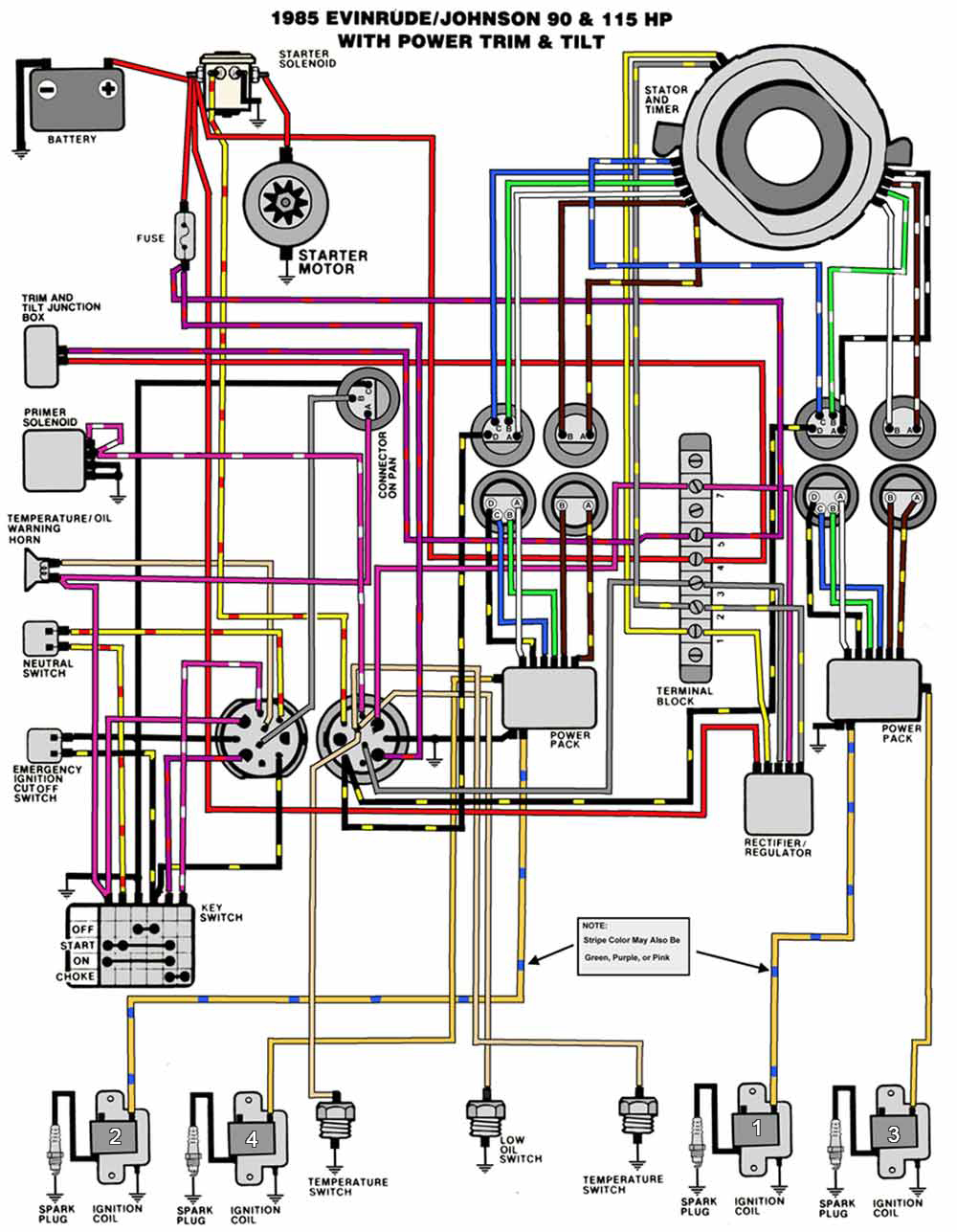
Here is a link to the parts diagram for your sterndrive. ..
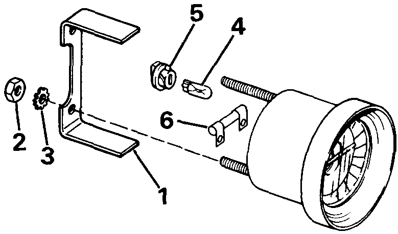
James, I had my boat repowered last year (OMC Cobra ). James.
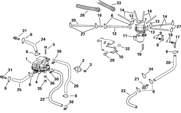
When re-wiring my c Evinrude TRIM gauge last weekend, I noticed that manual and I noticed a pictorial diagram that showed the wiring.Find great deals on eBay for omc trim gauge. Shop with confidence. wiring color codes Here is a listing of common color codes for EVINRUDE and JOHNSON outboard motors. These codes apply to later-model motors (approximately early 80’s to present).
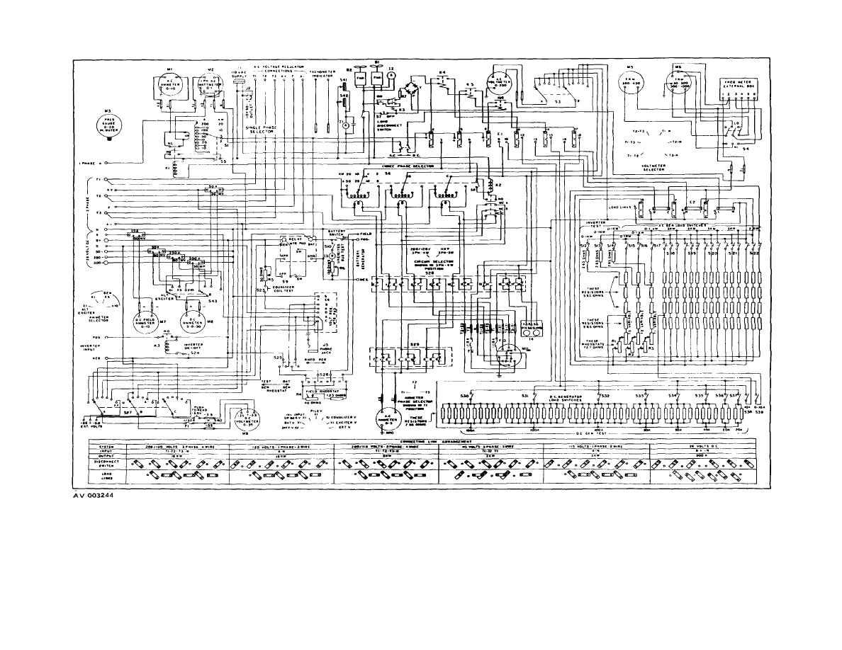
Tilt And Trim Gauge Wiring Diagram – Starting Know About Wiring omc trim gauge wiring diagram reinvent your wiring diagram u rh kismetcars co uk omc tilt Evinrude Etec Wiring Schematics – Reveolution Of Wiring Diagram • image from post johnson outboard motor ignition switch wiring rh vuutuut com evinrude etec wiring diagram. On some OMC TRIM gauges, for example the one I have, this direction is reversed, and the resting or no-current position of the gauge is at the right hand side.
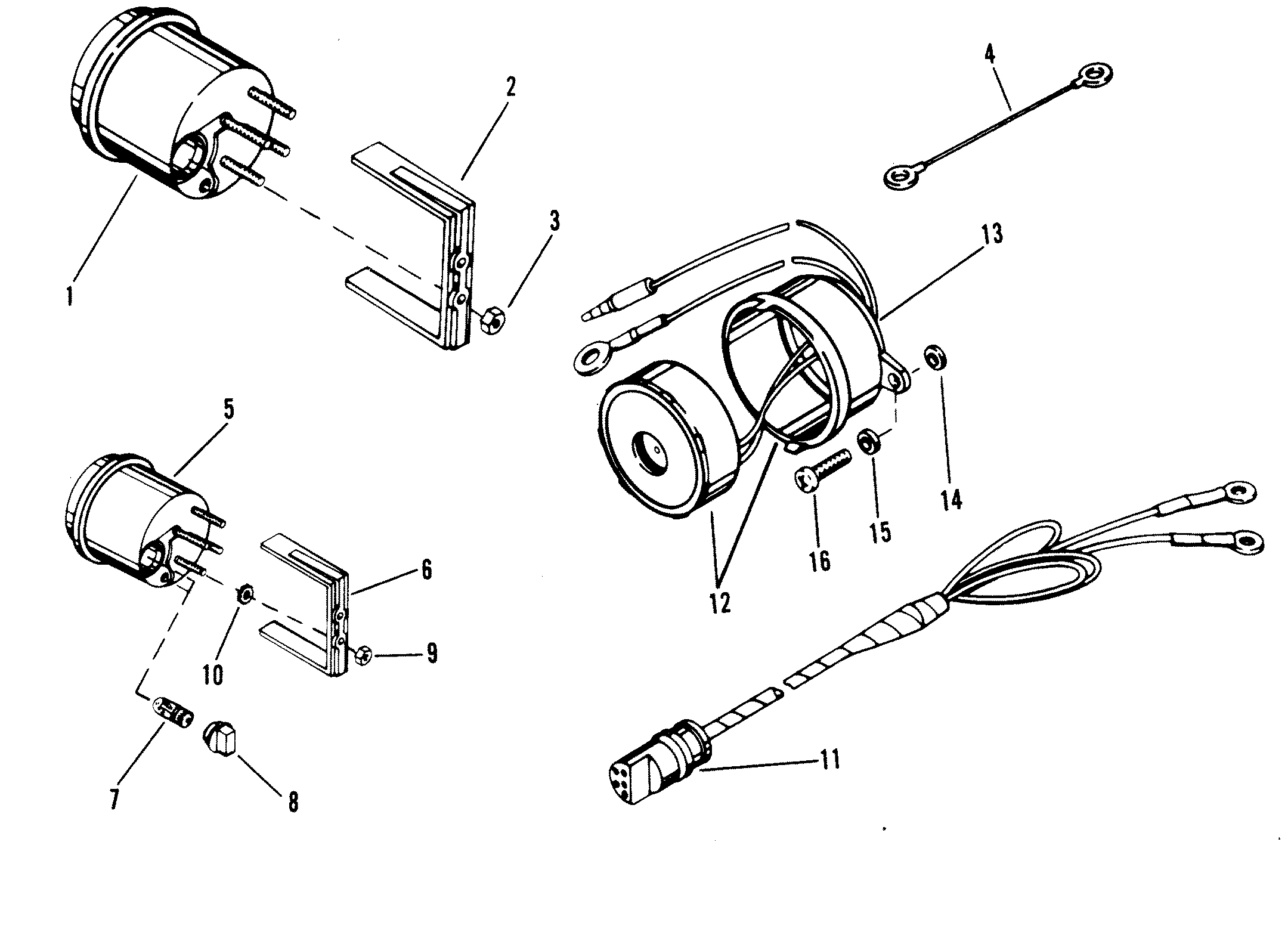
When more current flows the pointer moves to . The way the trim gauge is fairly simple, it all works on a resistance to ground principle. The trim sending unit on the side of the gimbal ring is a variable resistor.
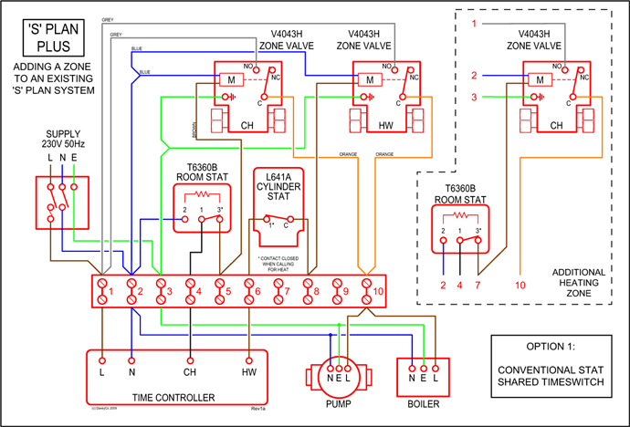
Do this, pull the gauge out, and leave all of the wires hooked up to it except for the sender (The S terminal wire) wire.50hp Johnson trim and tilt wiring question Page: 1 – iboats Boating Forums | OMC/Evinrude Trim Gauge Wiring c – Moderated Discussion Areas