Refer to Figure 1 to determine the proper size for the pump wires.
Control Panels
consultingthe Float Arrangement diagram appropriate for the control panel. The icons on the left represent several functions to facilitate your access to information in the digital publication.
play; pause. of.

Orenco. Refer to Figure 1 to determine the proper size for the pump wires. consultingthe Float Arrangement diagram appropriate for the control panel.
Septic pump three floats.
Refer to Figure 1 to determine the proper size for the pump wires. consultingthe Float Arrangement diagram appropriate for the control panel. Rev. © 05/01/ Panel Wiring Diagram. Model DAX2 IR2 RO.
Installation Manual – Orenco Controls
PCB. 20A.
Orenco S Series Control Panels
Pump 1. L1 L2 . during alarm conditions.
Installation Manual – Orenco Controls
Orenco Model. AHW or equiv.
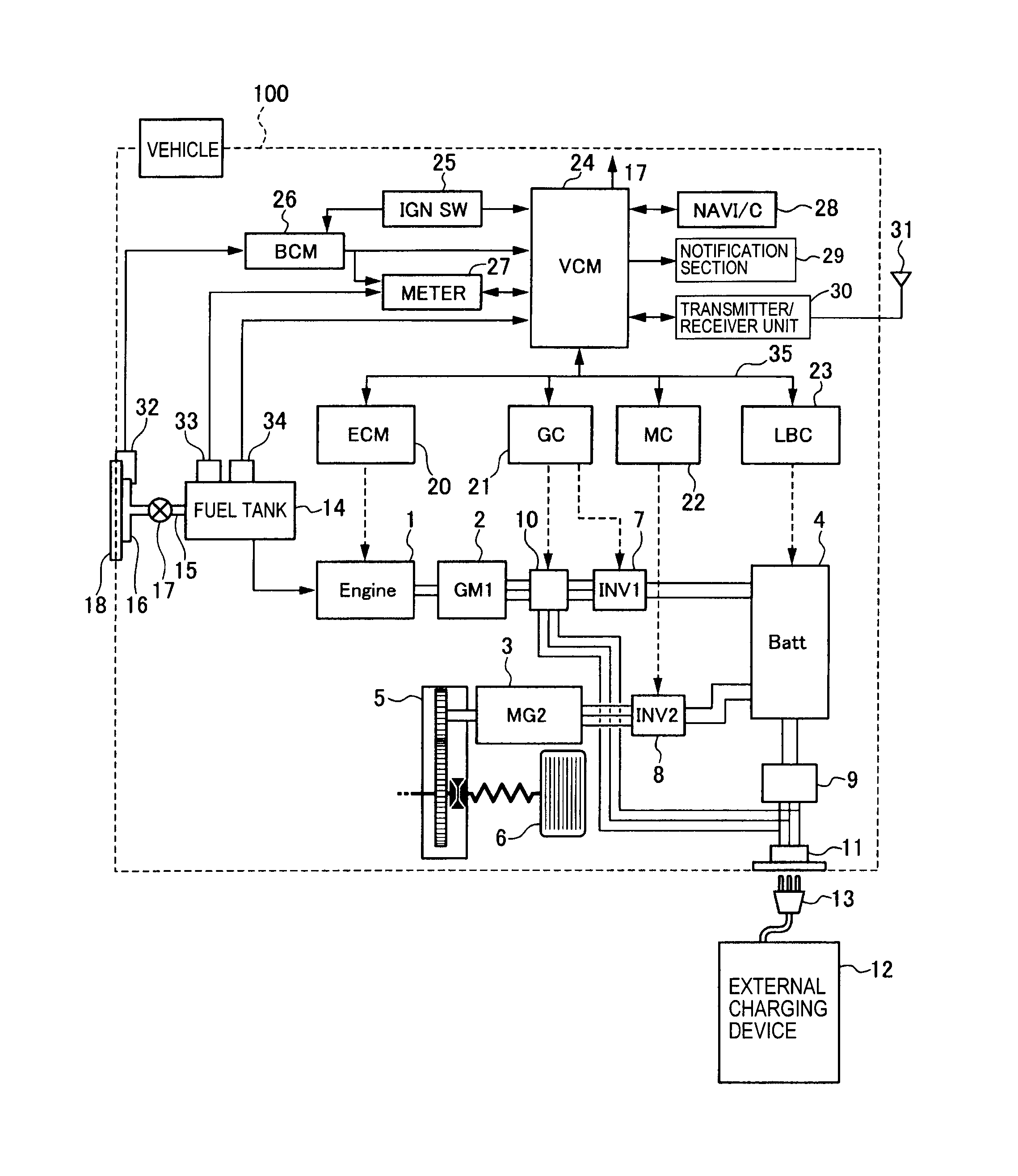
A. AL.Pump VAC / 3 Hp.
Alarms, Controls and Monitor Systems
1 Phase / 60 Hz. From Main Power Panel / VAC, 1 Phase, 60 Hz.
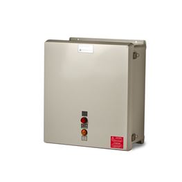
PCB 20A Pump L1 N NL2 EDW-WD-S-6 Rev. © 05/07/07 Panel Wiring Diagram.
Installation Manual – Orenco Controls
IR2 AUTO MAN M2 IR #1 3 Intrinsically Safe Section Non-Hazardous Non-Hazardous Area Safe Section Non-Intrisically SealingFt NOTE: A spacing of 2 inches (50mm) must be maintained b etw nir sc alyf,d non-intrinsically safe wiring. IR #2 3 94 ETM M1 A2A1 PRL G CT Options* X2X1 AUTO MAN 45 M2 L1 T1 M2.
AdvanTex Install Module 2 – Control Panel Install
The 4-in-1 Controller from Orenco Systems supports numerous electrical configurations and dosing schedules within a single panel. Both simplex and duplex models are available, and can be configured in the field for timed or demand dosing. control panel. Refer to the appropriate float arrangement diagram for the correct terminal connections for your system. 2.
Control Panels
Connect the wires coming from the pumps to the pump terminals. Refer to the panel wiring diagram for the correct terminal connections for your system. 3.
Connect the incoming power to the panel. Power to the panel must.
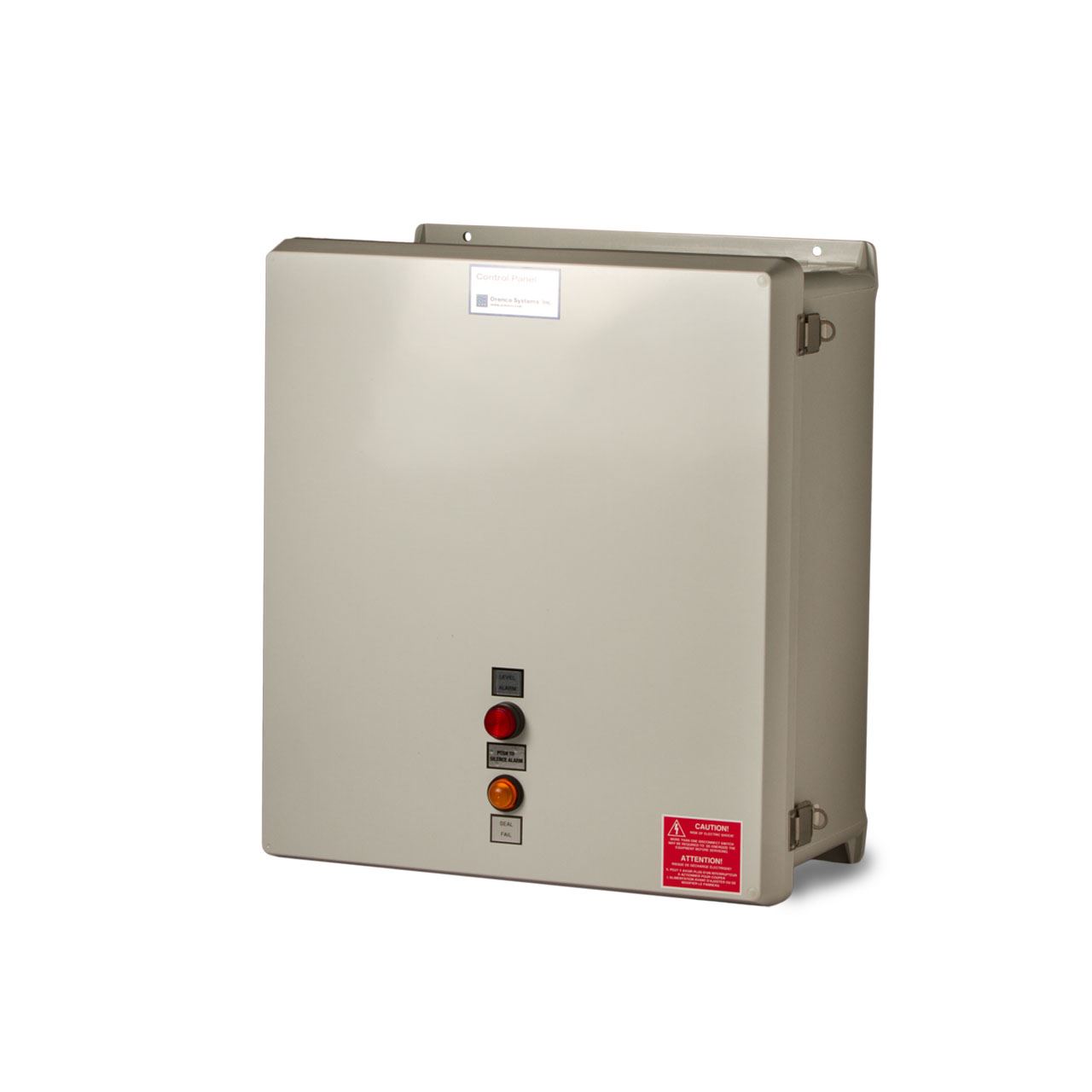
to the appropriate Float Arrangement diagram for the correct terminal connections. Connect the wires coming from the pump(s) to the pump terminals.
Control Panels
Refer to the panel wiring diagram for the correct terminal connections. Connect the incoming power to the panel. Power to the panel must be appropriate.Installation Manual – Orenco Controls Pages 1 – 16 – Text Version | FlipHTML5Internation Wastewater Technologies – Products