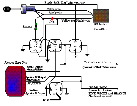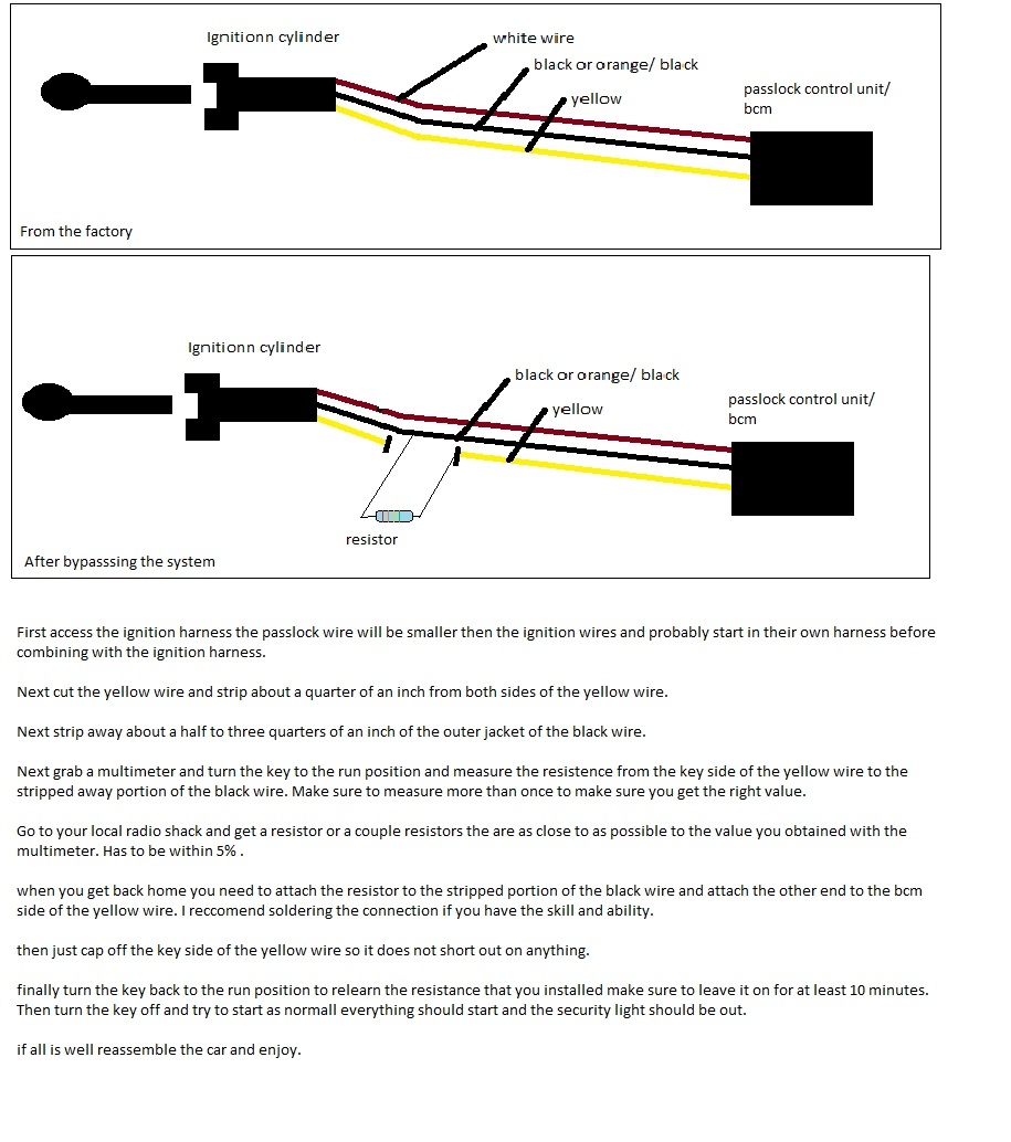
GM PASS- Key III Plus, bypass for vehicles equipped with the new style hybrid Passlock .
chart below will tell you by vehicle which wiring diagram to use. The GM Passlock System is a key-based, fuel shutdown, anti-theft system Passlock I Wiring Diagram This wire is located in the vehicle’s three-wire Passlock.
GM PASS- Key III Plus, bypass for vehicles equipped with the new style hybrid Passlock . chart below will tell you by vehicle which wiring diagram to use.
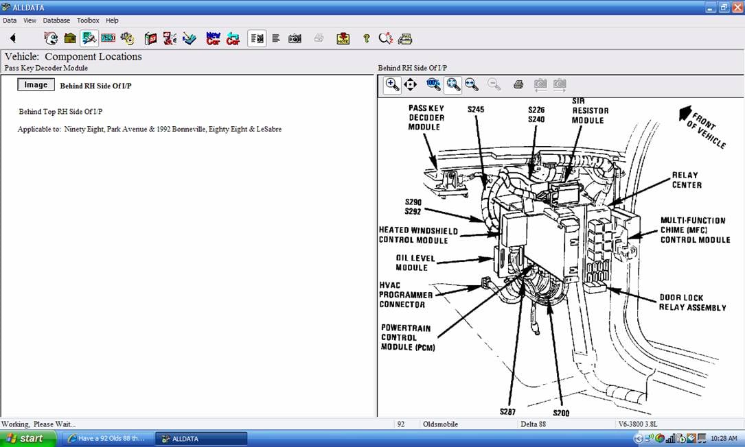
GM vehicles have three types of Vehicle Thief Deterrent (VTD) systems, each requiring their Vehicle Anti-Theft System (VATS), Passkey, & Passkey II – resistive chip ignition key . Place transmission in Park (automatic) or Neutral ( manual).
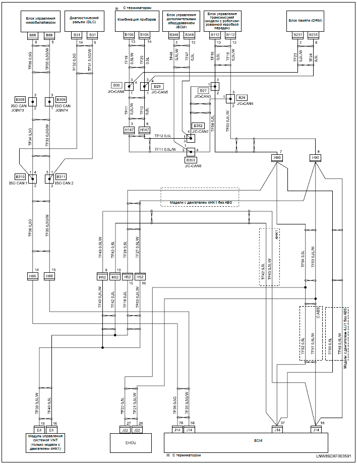
If you own a GM vehicle with PassKey III antitheft or a previous PassKey II or When you insert the key, electrical contacts mounted on the lock cylinder . removal and installation instructions, illustrations, wiring diagrams.How To Permanently Disable GM PassLock System.
By: Bain. On: July 18, In: Uncategorized. Passkey 1 and two have resistors in the keys.
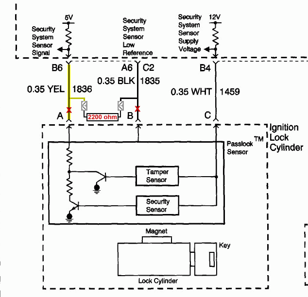
Passkey 3 uses a transponder in the key. The theft system was triggered when a street youth broke into my car and severed most of all the wiring in my steering column thinking they could hotwire my. Please study the following information carefully WHEN INSTALLING REMOTE START systems on a or later GM car or truck..
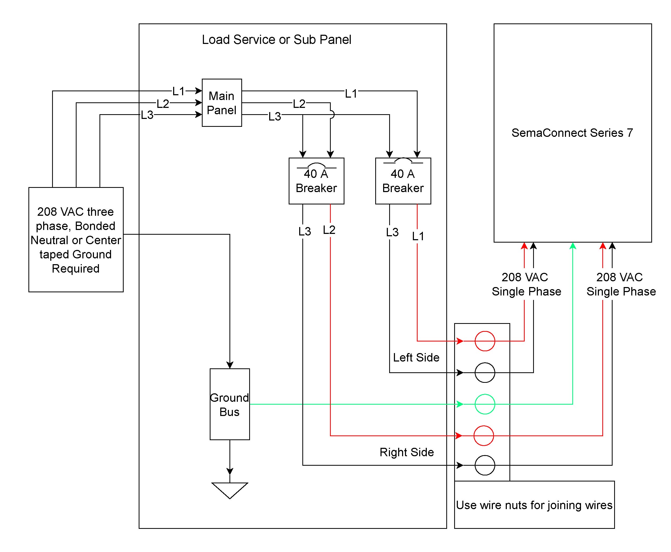
Introduced in , GM has changed the VATS anti theft system to Pass-Lock system. This is a similar device to the VATS system, in that there is .
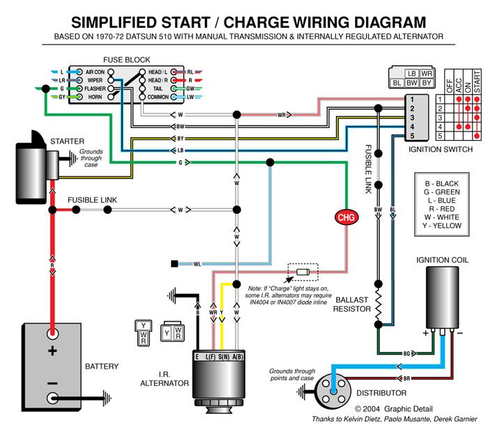
Passkey 3 Wiring Diagram passkey 3 wiring diagram bou onile passkey 3 wiring diagram inspirational passkey 3 wiring diagram fresh 94 ford ranger radio wiring diagram fresh block wiring diagram new chrysler radio wiring how to wire relays gm vehicle anti theft system passkey relay diagrams gm vehicle anti theft system passkey dozens of the. GM PASS- Key III Plus, bypass for vehicles equipped with the new style hybrid Passlock (resistance) and Passkey 3+ (transponder) type anti-theft system.
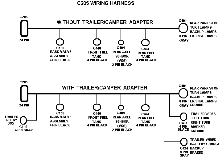
Chrysler transponder bypass kit for all 2nd generation encrypted Sentry key immobilizer. P BYPASS MODULE INSTALLATION DIAGRAM: for PASSLOCK 1 on GM Vehicles This is a BASIC Installtion Diagram used when Installing the Bypass Module to GM’s PASSLOCKI Anti-then System.
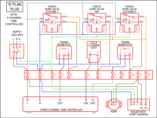
The wires that are needed for this Installation are marked in in this diagram. Transponde ring for Key Tran ponder Antenna PURPLE to BLACK BULB CHECK wire.GM Vehicle Anti-Theft System – Passkey II Relay Wiring DiagramHow To Permanently Disable GM PassLock System – KingBain
