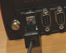
The PCAN-Explorer 6 is a professional program that operates in Windows® and The new and improved software allows for connections between multiple. PCAN-AU – User Manual.
3. Contents. 1 Introduction.
4. Properties at a Glance.
4. Scope of Supply.
5. 2 Connectors. 6.
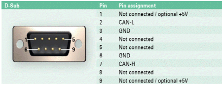
D-Sub Socket. Interfacing of CAN to USB is an intelligent CAN interface with a ARM 7 microcontroller.
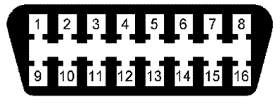
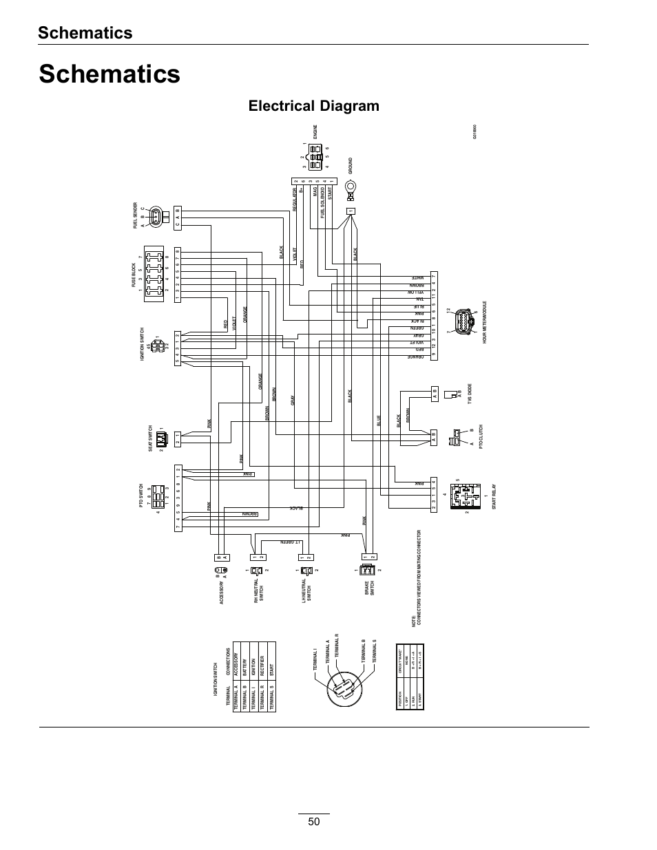
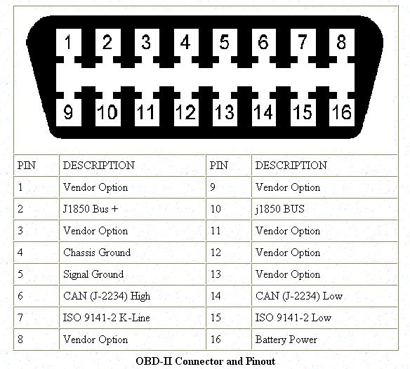
This article includes CAN bus interfacing with schematic diagram . If using the PEAK USB adapter on some of those devices, check the device information to ensure correct wiring.
The PCAN-USB manual. PCAN-USB – User Manual.

2. Relevant products.
Product name. Model.
Part number. PCAN-USB.
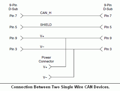
IPEH PCAN-USB opto-decoupled. Galvanic.Peak PAC SM65 Manuals Manuals and User Guides for Peak PAC SM Wiring Diagram 47 Peak PCAN-Wireless Gateway; Peak PCAN-Dongle; Peak PCAN-USB Hub; Peak PCAN-Router Pro; Peak PCAN-USB Pro FD; Peak PKC0BU4 Tx; Peak Categories.
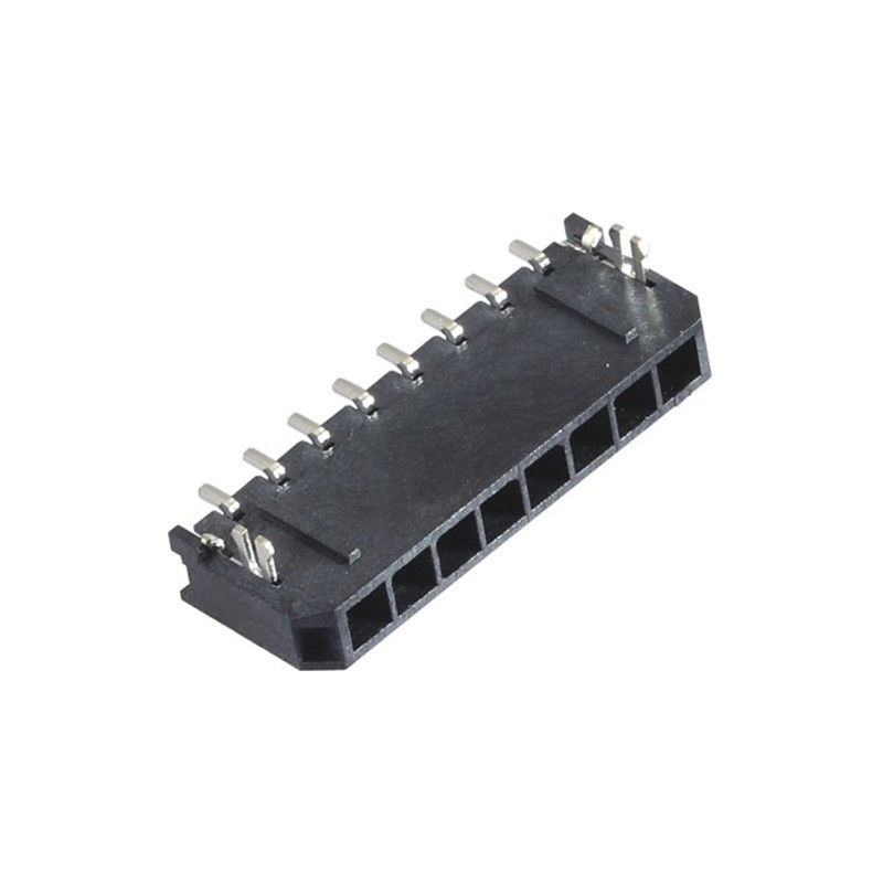
Laminator Recording Equipment PCI Card Adapter Inverter. PA Schematic PA System Schematic Diagram.
All PA Systems – from the smallest to the largest – follow the same basic format. The illustration below shows how the principal components common to most PA systems connect to each other.
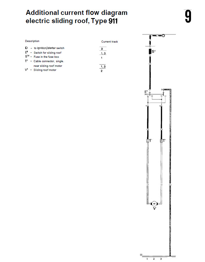
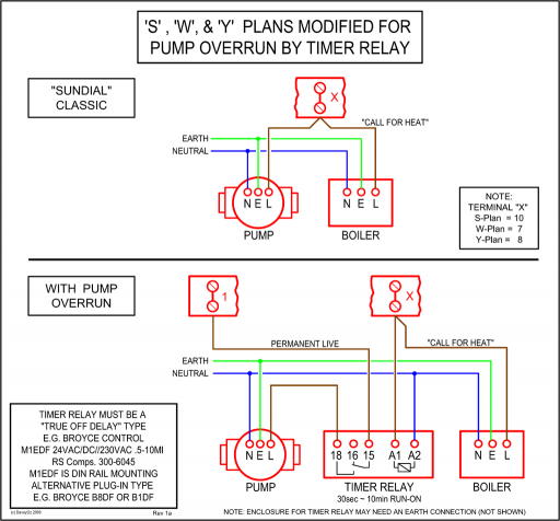
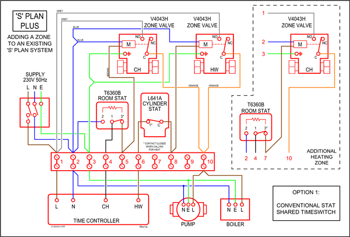
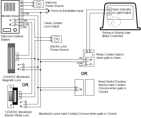
The system will all be low voltage to save on wiring costs. We now have the information to begin a wiring diagram.
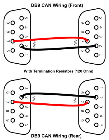
(We are not going to pick the devices by number that we need to do this job. Generic nomenclature will suffice, since we are demonstrating the making of a wiring diagram).
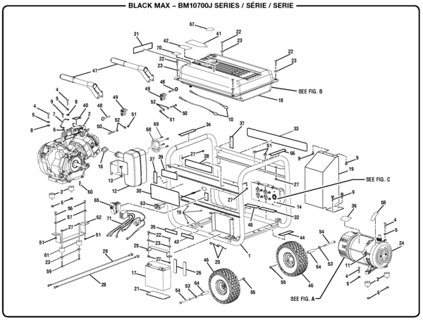
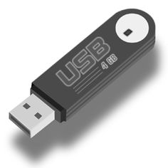
USB connectors. There are several types of USB connectors.
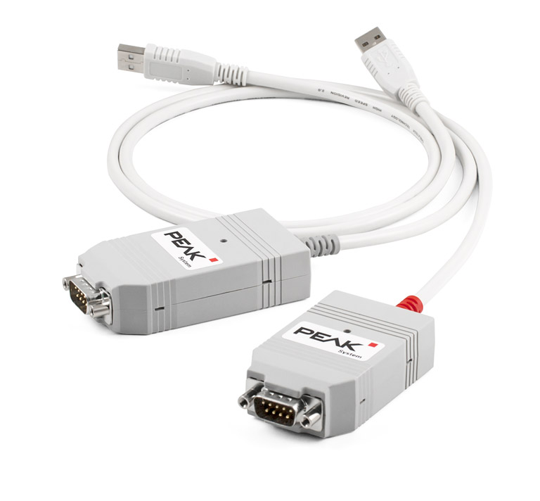
The connector mounted on the host or device is called the receptacle, and the connector attached to the cable is called the plug. CAN Bus Wiring Diagram, a Basics Tutorial.
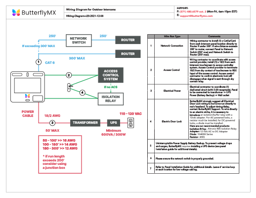
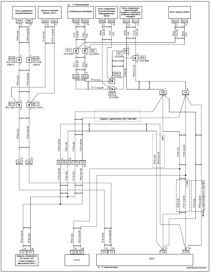
The CAN bus is a common digital network used in automotive, industrial, medical and scientific systems for routing sensor data between pieces of equipment. The main advantages are high resilience to noise, .LIN Connection Cable for PC LIN Interfaces: PEAK-SystemHow to Construct Wiring Diagrams | Industrial Controls
