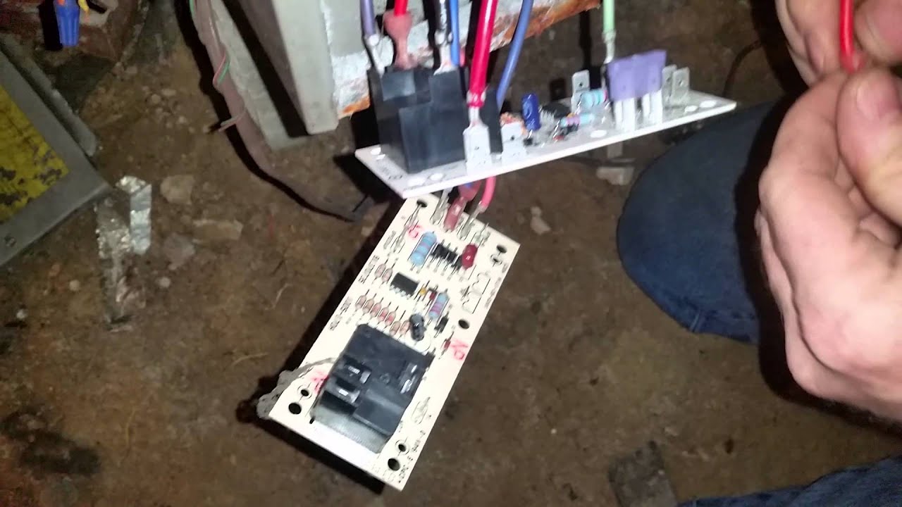
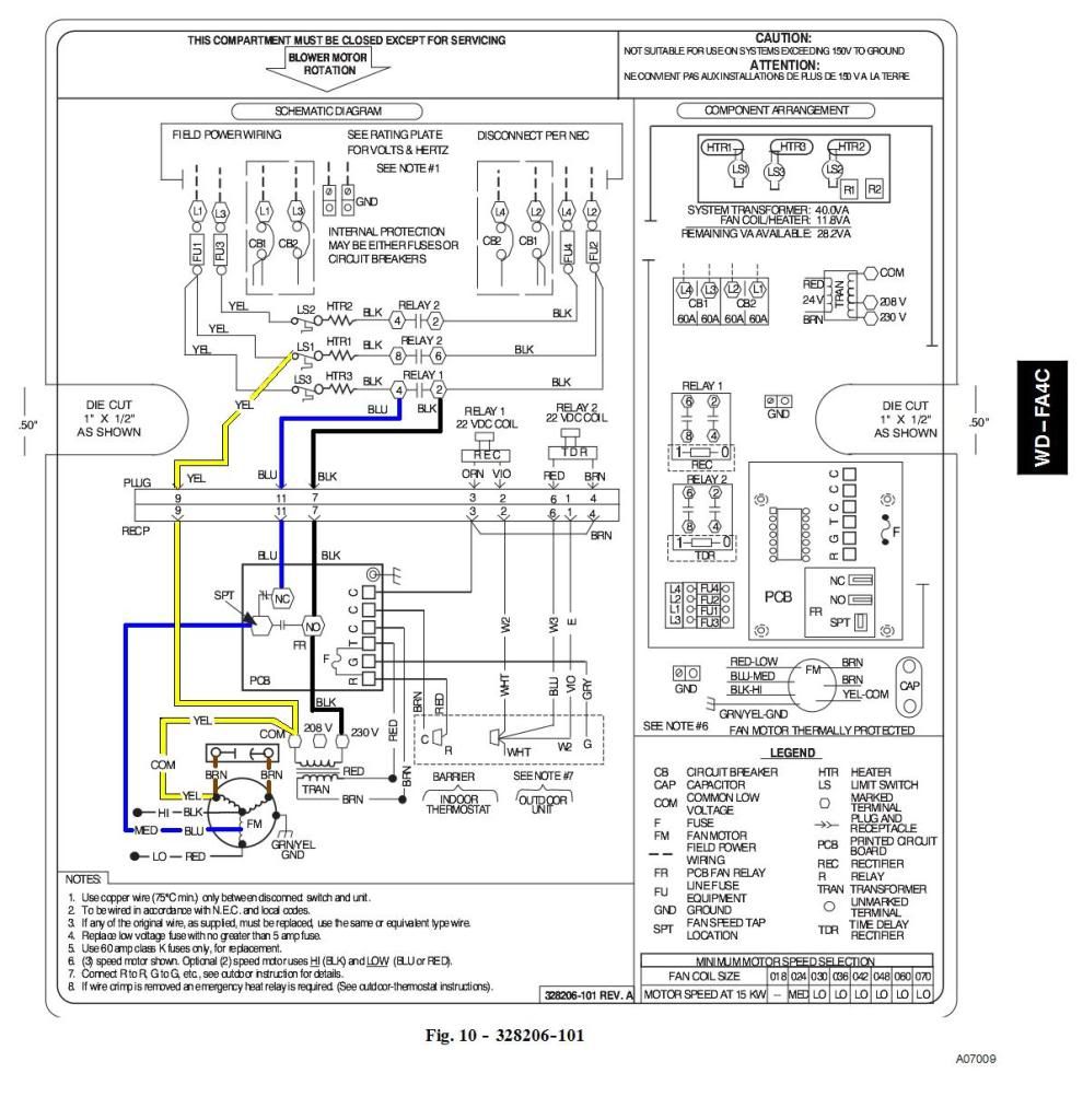
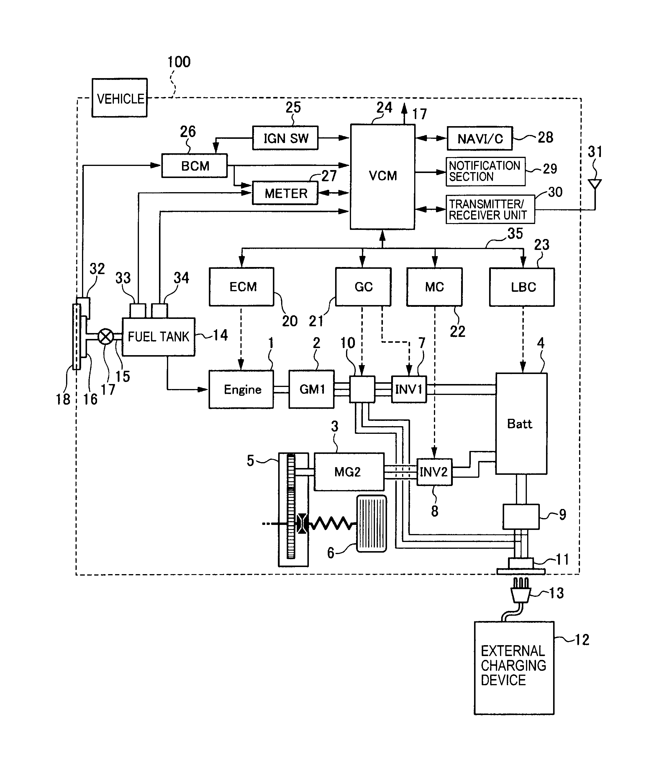
basic hvac wiring wiring diagram schemes hvac relays and sequencers hvac air Hvac Wiring Schematics 90 Relay – International hvac wiring diagrams together . Relay Wiring Diagram Inspirational Pcbfm Time Delay Relay.
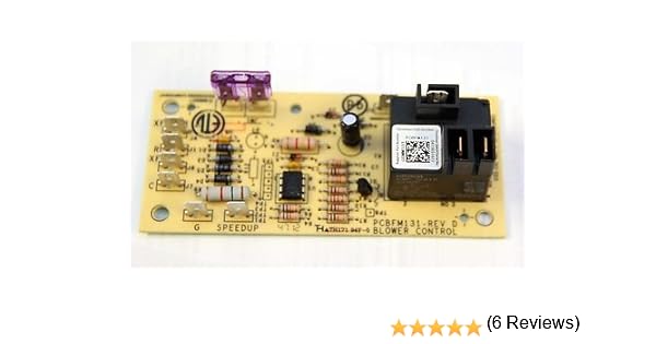
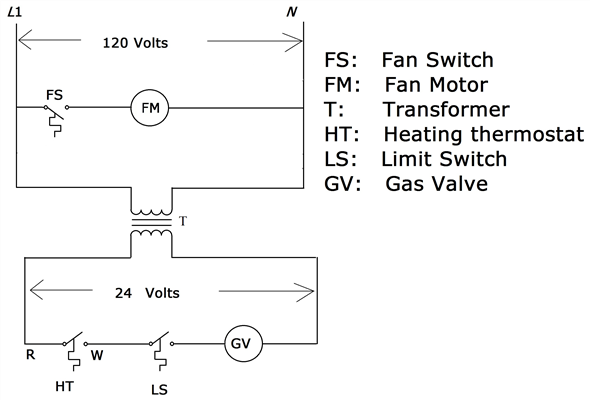
panasonic cq cu wiring diagram, outside ac unit wiring diagram, pick up guitar porsche wiring diagrams, piping a combi boiler diagram, pcbfm 11 pin relay wiring diagram time delay fuse chart time delay relay circuit diagram gas furnace thermostat wiring diagram time delay circuit diagram timer relay. Salt Dogg Wiring Diagram – Instruction Manual SHPE Salt Dogg lines, through pcbfm wiring diagram 23 wiring diagram images wiring diagrams salt.
(3) Wiring Diagrams. (1) Notice Label.
(1) Mounting Screw. (1) Bushing.
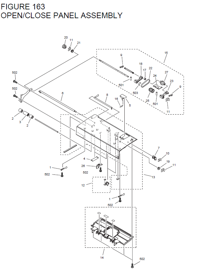
These instructions are primarily intended to assist qualified individuals experienced in.THERMOSTAT WIRING DIAGRAMS THERMOSTATS .. 13 INTRODUCTION Checking Product Received Upon receiving the product, inspect it for damage from shipment. Claims for damage, either shipping or concealed, should be filed immediately with the shipping company.
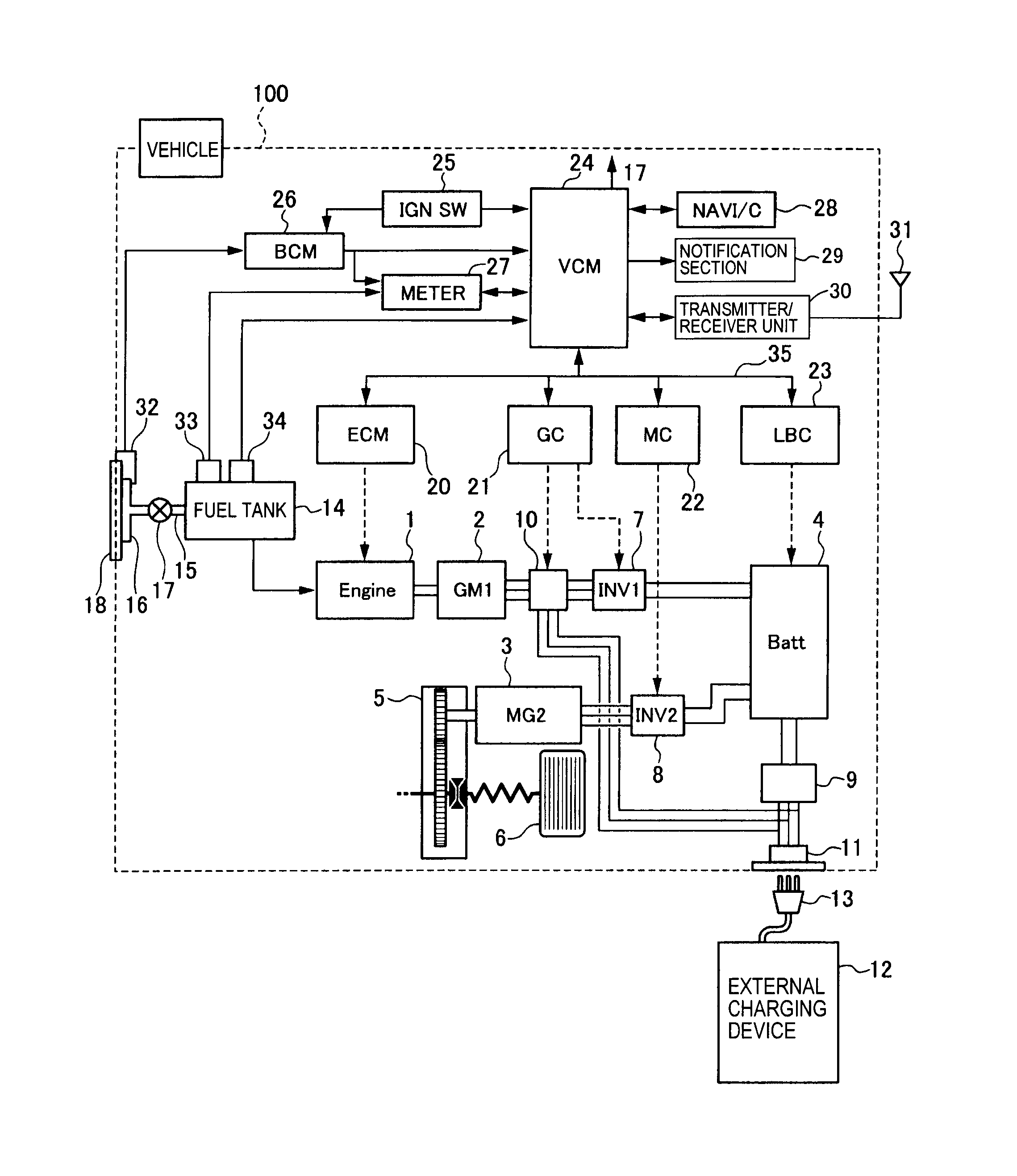
Pcbbfs Wiring Diagram Pcbfm Pcbdm New Shortstop Auto Reset Rhtechshoreclub: 3 Wire Sensor Diagram At schematron.org Code 3 Wiring Diagram Simple Schemarhschemawiretoday. Code 3 Wiring Diagram Simple Schemarhschemawiretoday: 3 Wire Sensor Diagram At schematron.org indoor blower motor. Under certain conditions the relay on the PCBFM Blower Control Board (EBTDR on the wiring diagram) could fail and weld the Normally Closed contacts closed.
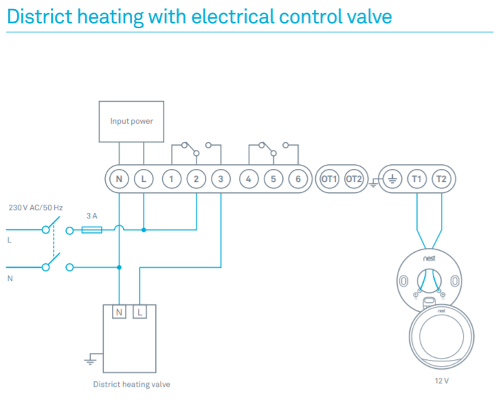
The diagram below shows the correct wiring for GPH13 heat pumps. There are 3 wires that should be checked and corrected if necessary. Posted by Unknown on 29th Oct Reasonable price, shipped real fast,easy install and took care of the problem.
Were Happy with the fan not running all the time!!5/5. REPAIR PARTS ARUF Air Handlers RPE This manual is to be used by qualified technicians only.
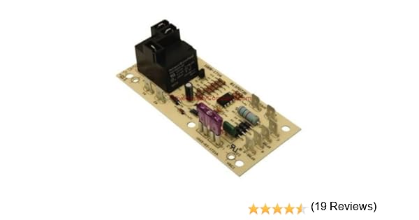
schematron.org schematron.org This manual replaces RPD PCBFM BOARD, ELECTRONIC BLOWER TIME DELAY RELAY CAPVAS CAPACITOR 10/V (M1, .PCBFM Goodman Time Delay Fan Control BoardBlower Control | Control Board | ICM Controls