
If you own a PCM marine engine or are considering buying one, understanding the wiring diagram is crucial for proper installation and maintenance. PCM, or Pleasure Craft Marine, is a leading manufacturer of marine engines, offering a wide range of models for various types of boats.
A PCM marine engine wiring diagram provides a detailed schematic of the electrical system, including connections, components, and their functions. This diagram is essential for troubleshooting electrical issues, installing new equipment, or simply understanding how the engine works.
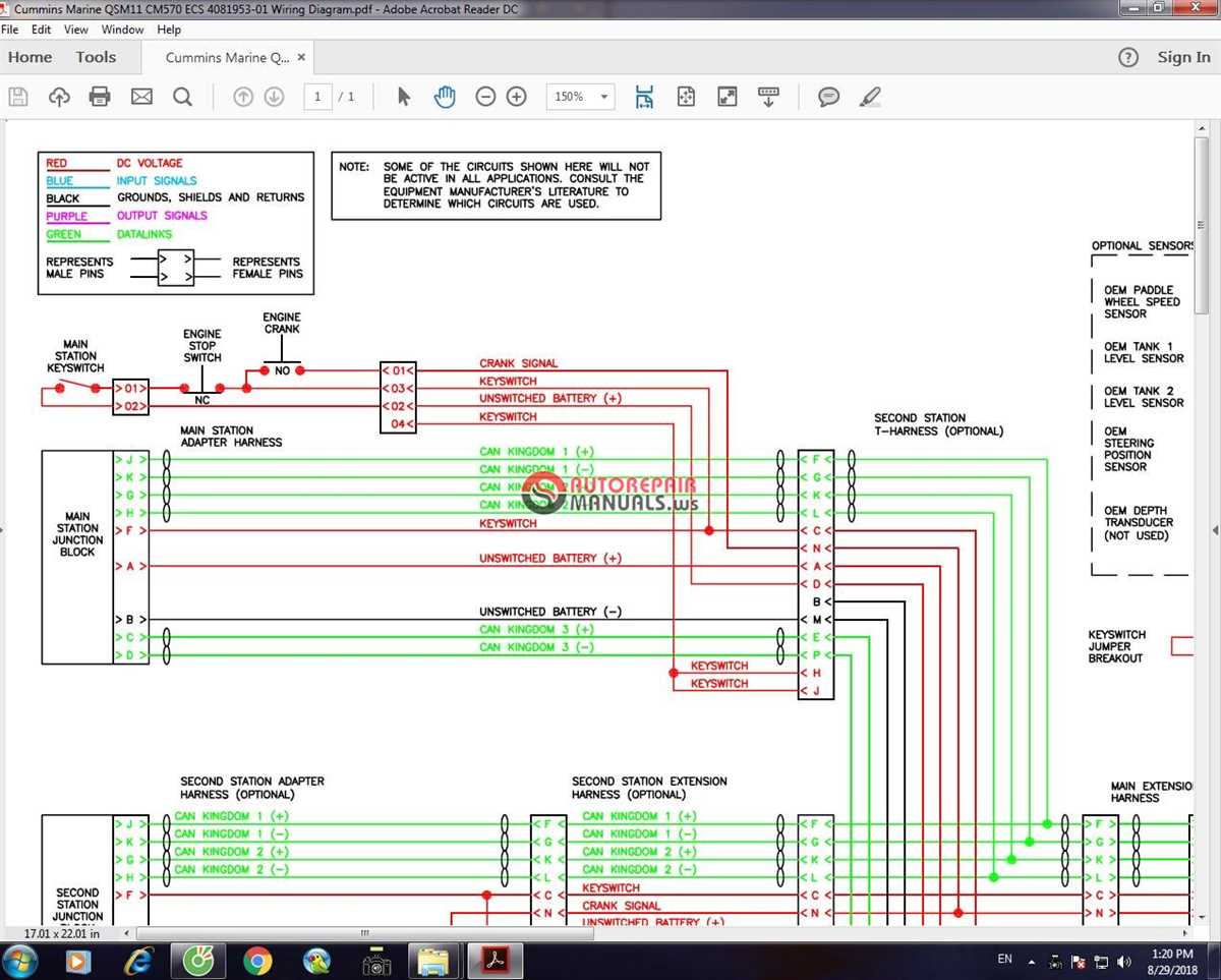
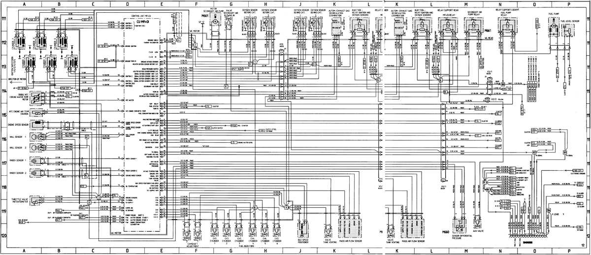
The wiring diagram typically includes a clear identification of wires, color codes, and connection points for various components such as the ignition system, fuel pump, sensors, and gauges. It also shows the battery connections, fuse locations, and grounding points, ensuring a safe and reliable electrical system.
By following the PCM marine engine wiring diagram, you can ensure that all the electrical connections are made correctly, reducing the risk of electrical malfunctions or potential hazards. Additionally, having a good understanding of the wiring diagram can help you identify and fix any problems that may arise, saving you time and money on repairs.
In this article, we will delve into the key elements of a PCM marine engine wiring diagram, explain their functions, and offer some tips on how to read and interpret the diagram effectively. Whether you are a seasoned boater or a beginner, this guide will provide you with the knowledge you need to navigate the electrical system of your PCM marine engine with confidence.
PCM Marine Engine Wiring Diagram
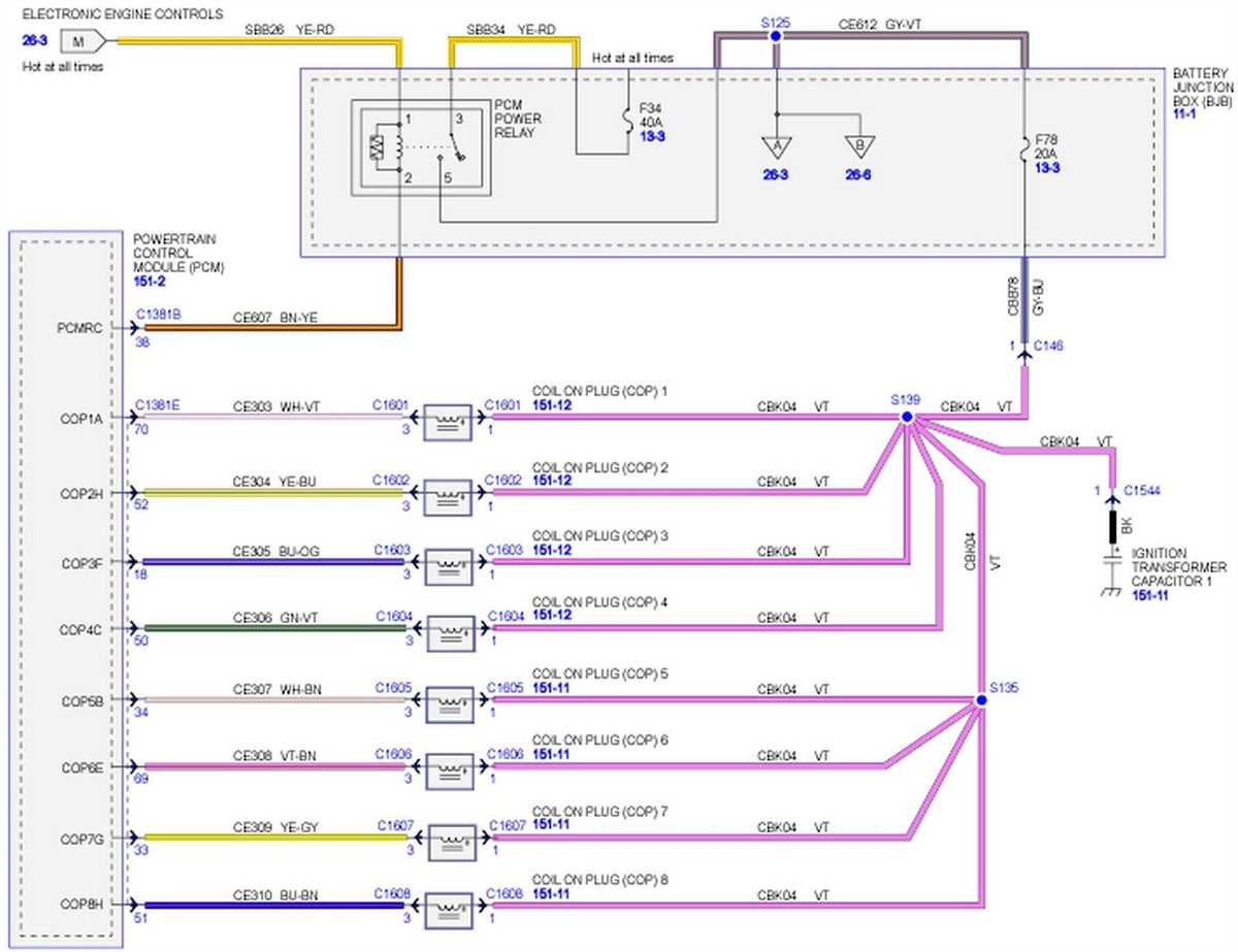
A PCM (Powertrain Control Module) marine engine wiring diagram is a schematic representation of the electrical connections and components of a marine engine that is equipped with a PCM. The PCM is a crucial component in modern marine engines as it controls the engine’s performance, fuel efficiency, and emissions. The wiring diagram provides a visual guide for technicians and boat owners to understand the electrical system of the PCM marine engine and troubleshoot any potential issues.
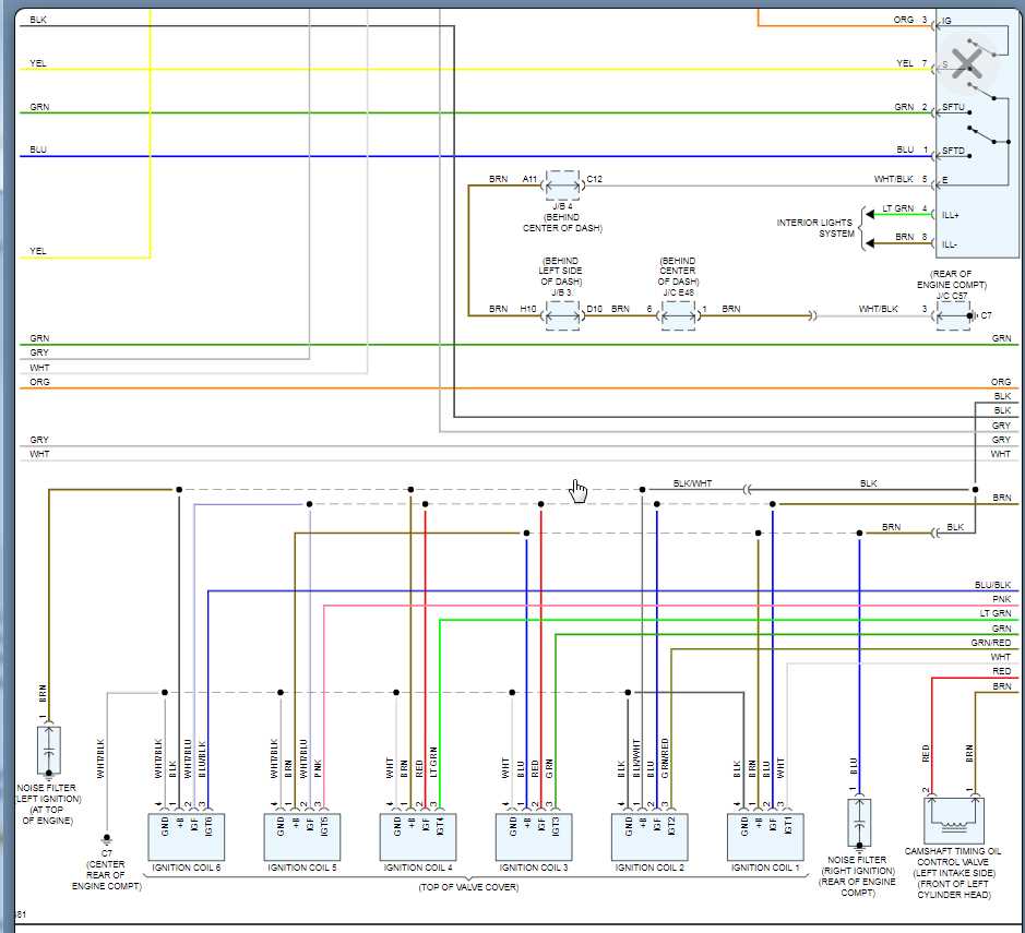
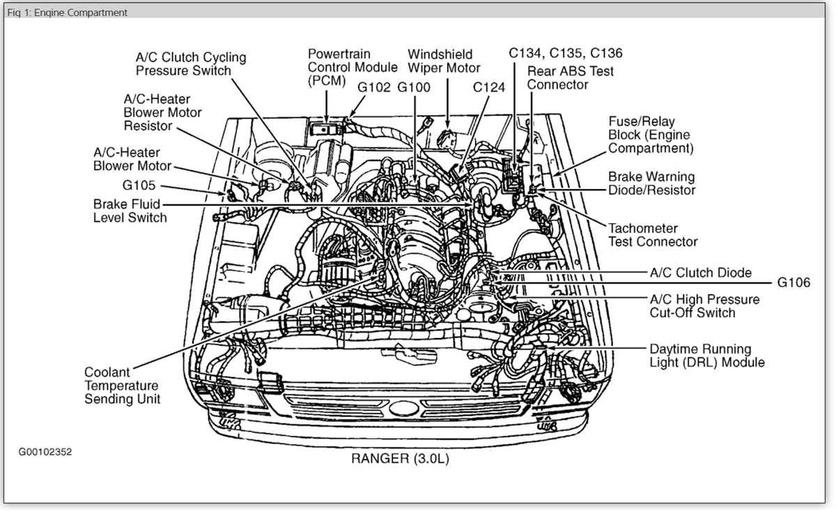
The PCM marine engine wiring diagram typically includes details such as wire colors, connector pins, component locations, and circuit routes. It shows how different components, such as sensors, actuators, relays, and switches, are interconnected to provide the necessary inputs and outputs for the engine’s operation. The diagram may also include information on fuse and relay locations, as well as any additional modules or devices that are part of the PCM system.
Understanding the PCM marine engine wiring diagram can be useful for several purposes. It allows technicians to diagnose and repair electrical problems, such as faulty sensors or damaged wiring harnesses. Boat owners can use the diagram as a reference for understanding how their engine’s electrical system works and to perform basic troubleshooting. Additionally, the diagram can be helpful when installing aftermarket components or making modifications to the engine’s electrical system.
About PCM Marine Engines
PCM (Power Control Marine) is a leading manufacturer of marine engines, known for their high-quality and reliable products. They specialize in producing inboard engines for recreational boats and have a wide range of models to suit various boat sizes and applications.
PCM marine engines are renowned for their performance and durability. They are designed to withstand the harsh marine environment and provide optimal power and efficiency. With advanced technologies and engineering, PCM engines offer exceptional fuel economy and smooth operation, ensuring a seamless boating experience.
The PCM marine engine lineup includes both gasoline and diesel engines, catering to different customer preferences and requirements. Their gasoline engines feature a range of horsepower options, allowing boat owners to choose the right amount of power for their specific needs.
One of the key advantages of PCM marine engines is their easy integration with boat systems and accessories. They come with comprehensive wiring diagrams and installation instructions, making it hassle-free for boat builders and technicians to install and connect the engine to other components. The PCM marine engine wiring diagram provides a clear visual representation of the electrical connections and ensures proper installation for optimal performance.
In addition to their engines, PCM also offers a range of accessories and parts to complement their marine power systems. These include alternators, starters, and cooling system components, among others. PCM is committed to providing excellent customer support and has a network of authorized dealers and service centers to assist boat owners with any issues or maintenance needs.
Overall, PCM marine engines are highly regarded in the boating industry for their performance, reliability, and ease of integration. Whether for recreational or commercial use, PCM engines offer a trusted solution for powering marine vessels and delivering a memorable boating experience.
Understanding the Wiring Diagram
The wiring diagram is a crucial component in understanding the electrical system of a PCM marine engine. It provides a visual representation of the connections between various components and their respective wiring. By studying the diagram, one can gain a deeper understanding of how the engine functions and how different parts are connected.
The diagram typically includes symbols and labels for different electrical components such as batteries, switches, relays, fuses, and wires. Each component is represented by a unique symbol, which helps to identify it easily. The connections between the components are usually shown using lines or arrows, indicating the flow of electrical current.
Key phrases:
- Electrical system: The wiring diagram provides insight into the electrical system of the PCM marine engine.
- Visual representation: The diagram visually represents the connections between different components.
- Components: Symbols and labels are used to represent components such as batteries, switches, relays, fuses, and wires.
- Connections: The diagram shows the connections between different components using lines or arrows.
- Flow of electrical current: The lines or arrows in the diagram indicate the direction of the electrical current.
Understanding the wiring diagram is essential for troubleshooting electrical issues, making modifications, or installing additional components. It allows technicians and boat owners to identify potential problems, locate specific wires or components, and ensure proper connections. By following the diagram, one can effectively diagnose and resolve any electrical problems that may arise in a PCM marine engine.
Common Wiring Diagram Components
In a PCM marine engine wiring diagram, several components are commonly included to provide a clear understanding of the electrical system. These components play vital roles in ensuring proper functionality and safety in the operation of the marine engine.
1. Battery
The battery is a key component in the electrical system. It supplies the initial power required to start the engine and provides continuous power for various electrical components. The wiring diagram will typically show the connection points for the positive and negative terminals of the battery.
2. Ignition Switch
The ignition switch is responsible for starting and stopping the engine. It provides the necessary connection between the battery and the starter motor. The wiring diagram will display the wiring connections for the ignition switch, including any safety interlocks or wiring for additional accessories.
3. Starter Motor
The starter motor is crucial for starting the engine. It takes power from the battery and spins the engine’s flywheel, which allows the engine to start running. The wiring diagram will illustrate the wiring connections for the starter motor, including any solenoid or relay that may be required.
4. Alternator/Charging System
The alternator is responsible for charging the battery and providing power to the electrical components while the engine is running. The wiring diagram will show the connections for the alternator and any associated regulators or diodes that control the charging system.
5. Instrument Panel
The instrument panel houses various gauges and controls that allow the operator to monitor and control the engine’s performance. The wiring diagram will include the wiring connections for the instrument panel, including connections for gauges, switches, and warning lights.
Overall, a PCM marine engine wiring diagram includes these common components to provide a comprehensive overview of the electrical system. Understanding these components and their wiring connections is essential for troubleshooting and maintaining the marine engine’s electrical system.
Essential Steps for Wiring a PCM Marine Engine
Wiring a PCM marine engine requires careful planning and attention to detail to ensure a reliable and safe electrical system. Here are some essential steps to follow when wiring a PCM marine engine:
1. Gather the necessary tools and materials:
- Wire cutters and strippers
- Electrical tape
- Crimping tool
- Wire connectors
- Fuse holder and fuses
- Heat shrink tubing
- Wire loom
2. Create a wiring diagram:
Before starting the wiring process, it is important to create a detailed wiring diagram. This will serve as a guide and help ensure that all connections are made correctly. Include all components of the PCM marine engine, such as the ignition coil, starter motor, fuel pump, and sensors.
3. Disconnect the battery:
Prior to any wiring work, disconnect the negative battery cable to prevent accidental shorts or electrical shock.
4. Route and secure the wiring:
Carefully route the wiring to avoid sharp edges or hot surfaces that could damage the insulation. Use wire loom, zip ties, or other securing methods to keep the wiring organized and prevent it from coming in contact with moving parts.
5. Make proper connections:
Strip the ends of the wires and use the appropriate connectors to make secure and reliable connections. Crimp the connectors using a crimping tool, and then cover them with heat shrink tubing to provide additional protection against moisture and corrosion.
6. Install fuse protection:
Install a fuse holder and the appropriate fuses to protect the electrical system from overloads. Refer to the wiring diagram to determine the correct fuse ratings for each circuit.
7. Test the electrical system:
After completing the wiring, connect the battery and test the electrical system to ensure proper functionality. Use a multimeter to check for any voltage drops or continuity issues.
By following these steps and paying close attention to the details, you can successfully wire a PCM marine engine and have a reliable and safe electrical system for your boat.
Troubleshooting Common Wiring Issues
In the process of installing or troubleshooting a PCM marine engine wiring system, there are several common issues that can arise. These issues can cause electrical malfunctions, engine performance problems, and even potential safety hazards. It is important to be aware of these issues and know how to troubleshoot them effectively.
1. Loose or Corroded Connections
A common wiring issue is loose or corroded connections. Over time, the vibrations of the boat can cause wiring connections to loosen or become corroded, leading to poor electrical conductivity and intermittent electrical problems. To troubleshoot this issue, visually inspect all wiring connections and terminals, making sure they are tight, secure, and free of corrosion. If any connections are loose, tighten them using the appropriate tools. If there is corrosion present, clean the affected area with a wire brush or contact cleaner.
2. Faulty Grounds
Another common wiring issue is faulty grounds. Ground connections provide a path for electrical current to return to the battery. If there is a poor or intermittent ground connection, it can cause various electrical malfunctions and system failures. To troubleshoot a faulty ground, check all ground connections to ensure they are clean, tight, and securely fastened to a clean metal surface. If necessary, clean the connection points and tighten them accordingly.
3. Blown Fuses
Blown fuses are a common problem in marine engine wiring systems. Fuses are designed to protect electrical circuits from excessive current flow. If a fuse blows, it indicates an electrical overload or short circuit. To troubleshoot this issue, check all fuses in the wiring system and replace any blown fuses with the appropriate amperage rating. It is also important to identify the root cause of the electrical overload or short circuit and address it to prevent future fuse blowouts.
4. Misrouted or Damaged Wiring
Misrouted or damaged wiring can cause a variety of electrical problems in a marine engine wiring system. Wires that are pinched, frayed, or chafed can lead to short circuits, poor connections, and even electrical fires. To troubleshoot this issue, visually inspect all wiring for any signs of damage. If any wires are found to be misrouted or damaged, repair or replace them as necessary, ensuring they are properly routed and secured away from any potential sources of damage.
5. Incorrect Wiring Connections
Incorrect wiring connections can also cause issues in a marine engine wiring system. This can occur during the initial installation or when making repairs or modifications. To troubleshoot this issue, refer to the wiring diagram specific to your PCM marine engine and double-check all wiring connections against the diagram. Make sure each wire is connected to the correct terminal or component as per the diagram. If any incorrect connections are identified, correct them accordingly.
Conclusion
Properly diagnosing and troubleshooting wiring issues in a PCM marine engine is crucial for maintaining optimal electrical performance and ensuring the safety of the vessel. By being aware of common wiring issues like loose connections, faulty grounds, blown fuses, misrouted or damaged wiring, and incorrect connections, boat owners and technicians can effectively troubleshoot and resolve these problems. Regular inspection and maintenance of the wiring system are also recommended to prevent these issues from occurring in the first place.