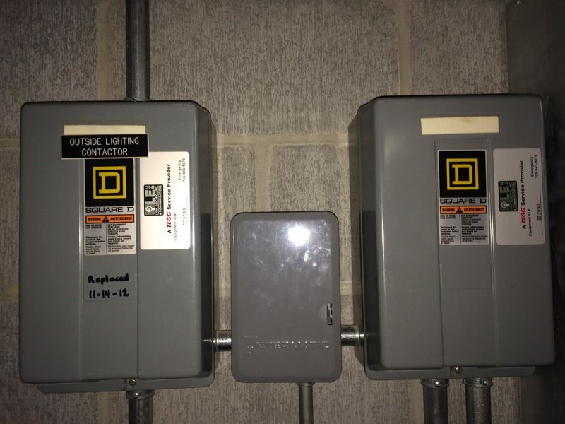
Photocells and timers are switches that turn on and off automatically. Photocells are A time clock has a built-in clock.
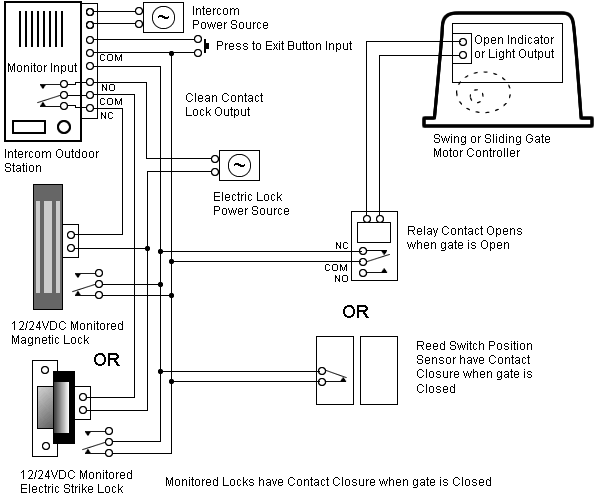
Photocell and Timer Wiring Diagram 1. 2) Copy following link for several timer wiring diagrams.
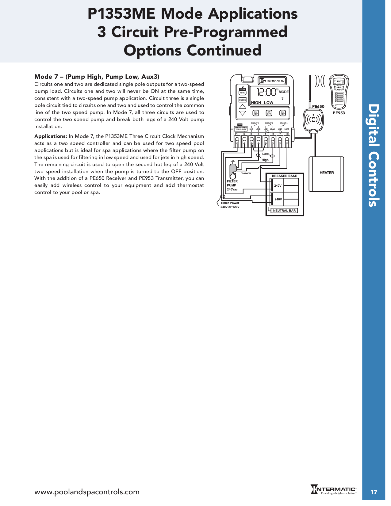
The photo cell is basically a switch, and the timer is also a switch. 2 switches can. [EBOOKS] Time Clock Photocell Wiring Diagram PDF [BOOK].
Book file PDF easily for everyone and every device. You can download and read.
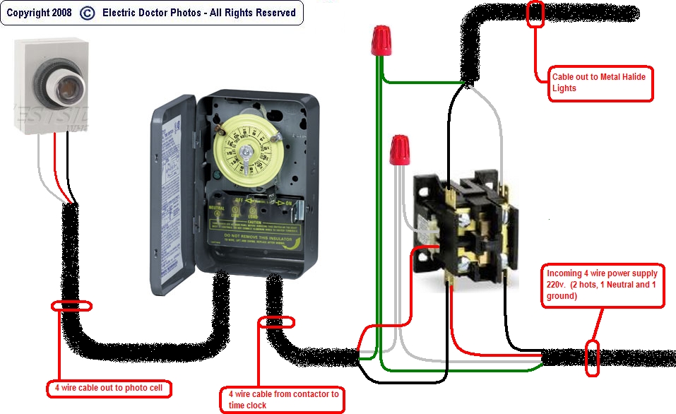
wiring for lights connected to timer and photocell if anybody could help and possible provide a diagram i would be most greatfull. and off at say midnight then connect the photocell supply and timeclock supply terminals to.
[EBOOKS] Time Clock Photocell Wiring Diagram PDF [BOOK]. Book file PDF easily for everyone and every device.
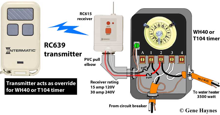
You can download and read.Apr 12, · I figure putting a photocell and a timeclock in series with a lighting contactor coil will do the trick. I will set the timeclock to turn on at 4 pm. Boss does not want an astromical time clock for whatever reason.
Oct 07, · Often the photocell is used to turn the lights on, the timeclock is used to turn them off shortly after closing time. If that is the case you should find the clock motor fed independantly of the contacts in the timeswitch.
from the timeclock the contactor is fed to throw your lighting circuits on and off. Nov 30, · wiring for lights connected to timer and photocell. Discussion in ‘Electrics UK’ started by however if you want the light to come on at dusk and off at say midnight then connect the photocell supply and timeclock supply terminals to permanent live & neutral then the output through the timeclock terminals set the clock to come on at say.
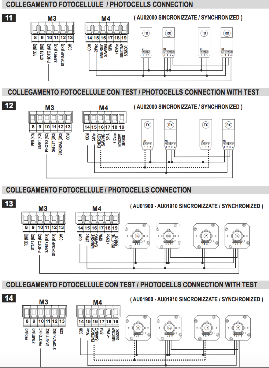
Jun 15, · Just to spell it out, the timeclock AND the photocell will be powered all the time. But as has been found, the photocell has a warm up period, so does not like being powered down.
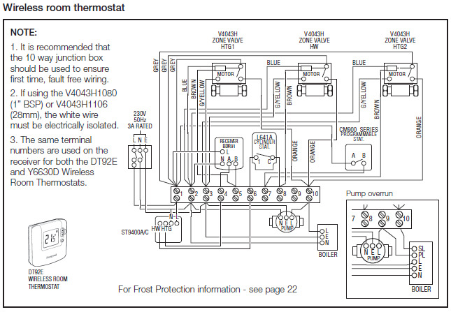
So output from photocell, via volt free contact of timeclock to contactor. Photocell and Timer Wiring. Photocell and timer switch wires each have a line (black), load (red), neutral (white), and ground (green).
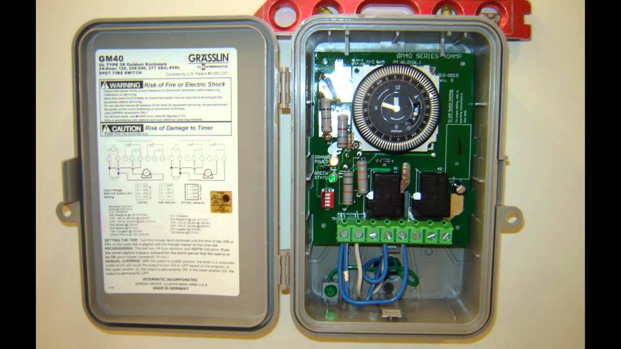
The black line wire connects to line voltage from the panel, the red load wire connects to the light(s), the white neutral wire connects to the neutral wires of the circuit.Lighting control wiring diagram / detail ?Timeclock and photocell – ECN Electrical Forums