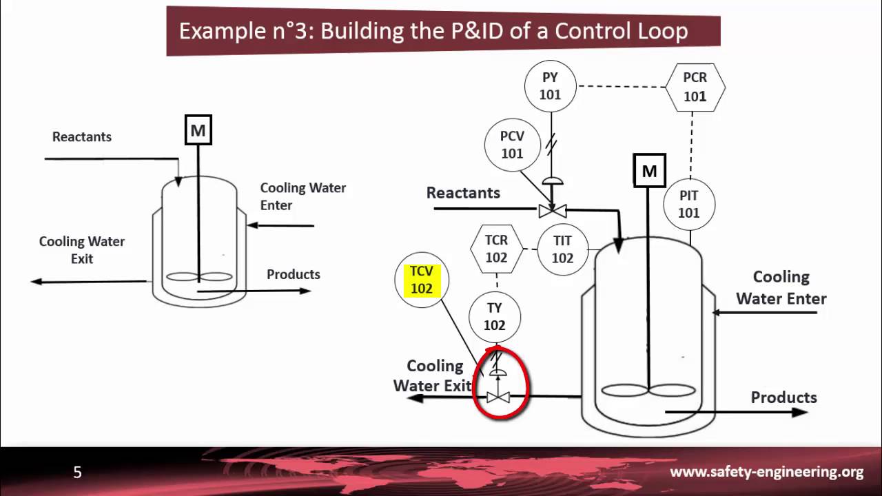
P&ID for short.
In this blog post, you will learn all about P&ID Diagrams. For example, let’s take a look at a pneumatic system P&ID. First, you.

A piping and instrumentation diagram, or P&ID, shows the piping and related . If you use software to create your P&IDs, there are some basic steps to follow.
Piping & Instrument Diagrams: How it works Elements of a P&ID Example-. 2 ” dia., Type s/s pipe in acetic acid reactor discharge service, insulated with.
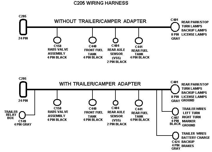
Piping and instrumentation diagram, also called P&ID, illustrates the piping processes and interactions with other installed equipment and instrumentation. Here, I have tried to explain P&ID and PEFS an easy way.
Piping and instrumentation diagram is also known as Process engineering flow scheme which is.A piping and instrumentation diagram (P&ID) is a detailed diagram in the process industry which shows the piping and vessels in the process flow, together with the instrumentation and control devices. Superordinate to the piping and instrumentation flowsheet is the process flow diagram.
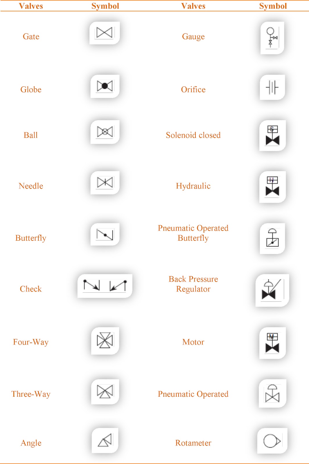
What are Piping & Instrumentation Diagrams. What are your P&ID needs?
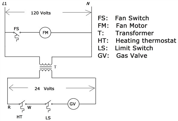
I’m new to P&IDs and want to learn more. A piping and instrumentation diagram, or P&ID, shows the piping and related components of a physical process flow.
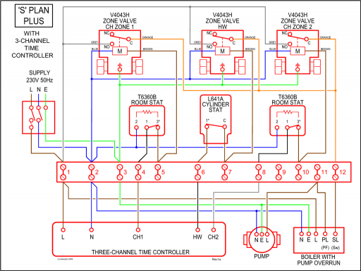
Basic start up and operational information; When to . Nov 07, · What is P & ID?
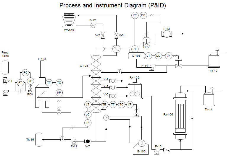
A Process and Instrumentation Diagram (P & ID) shows the process flow and interconnection of process equipment which is used control a process. The P & ID includes every mechanical aspect of the plant except stream flows, pipe routing, pipe lengths, pipe fittings, supports, structure & foundations. Piping and instrumentation diagram plays a crucial role in the design and engineering of process plants and piping systems, by showing the interaction of process used to control the process.
P&ID is a schematic illustration of functional relationship of piping, instrumentation and . P&ID – Piping and Instrumentation Diagram P&ID is a schematic illustration of a functional relationship between piping, instrumentation and system components.Learn How to Read P&ID Drawings – A Complete GuidePiping and instrumentation diagram – Wikipedia
