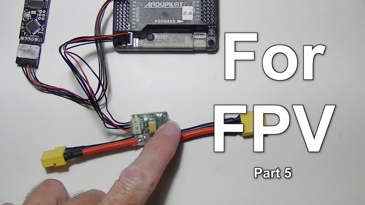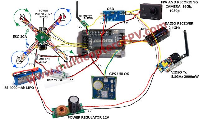
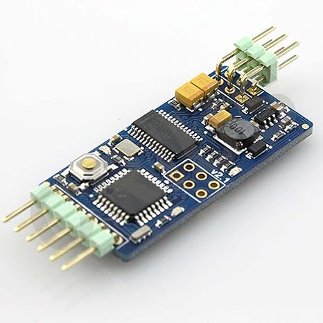
Pixhawk; APM; MinimOSD on ground side. Introduction. MinimOSD is a an open-source OSD (on screen display) for FPV, which is able to Ultimate LRS wiring diagram · Using Ultimate LRS + OrangeRX with a Bluetooth module.
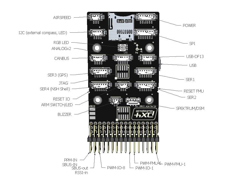
The Pixhawk® XRacer board family is optimized for small racing quads and planes. Power module (with voltage and current sensing); I2C splitter ( supporting Wiring Diagrams Grau setup pixracer bottom TELEM1, TELEM2+OSD ports. Ground Control Stations (GCS), On-Screen Displays (OSD), Companion Computers, and other MAVLink peripherals interact with PX4 using separate MAVLink.
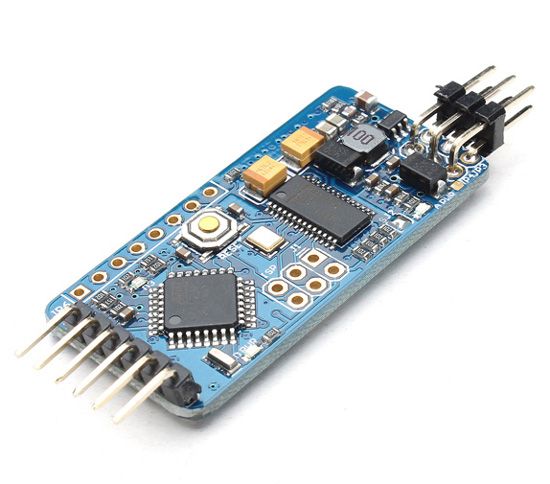
The Minim OSD (On Screen Display) is a small circuit board that pulls telemetry data from your APM or Pixhawk See under “Files” tab for wiring diagram. .
PixFalcon Micro PX4 Autopilot plus Micro M8N GPS and Mega PBD Power Module. For more detailed instructions please refer to the MinimOSD Project wiki. Note To connect to Pixhawk, use this DF13 6-pin cable to connect to the TELEM2 port.
. If using git clone, also do a git submodule init and git submodule update.Pixhawk Mini (Discontinued) This product is no longer manufactured or available from 3DR.
The 3DR ® Pixhawk ® Mini autopilot is a next-generation evolution of the Pixhawk (designed by 3DR in collaboration with HobbyKing ®).It is about 1/3rd the size of the original Pixhawk and has more powerful processors and sensors. Jun 27, · Hello, I’m trying to configure MinimOSD for Pixhawk and run into a problem.
Wiring an FPV camera, video switch, minimosd, GoPro and VTX
I installed minimosd-extra firmware on it, performed configuration. Pixhawk Wiring Quick Start.
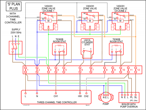
The diagram shows a combined GPS and Compass. The GPS/Compass should be mounted on the frame as far away from other electronics as possible, with the direction marker towards the front of the vehicle (separating the compass from other electronics will reduce interference).
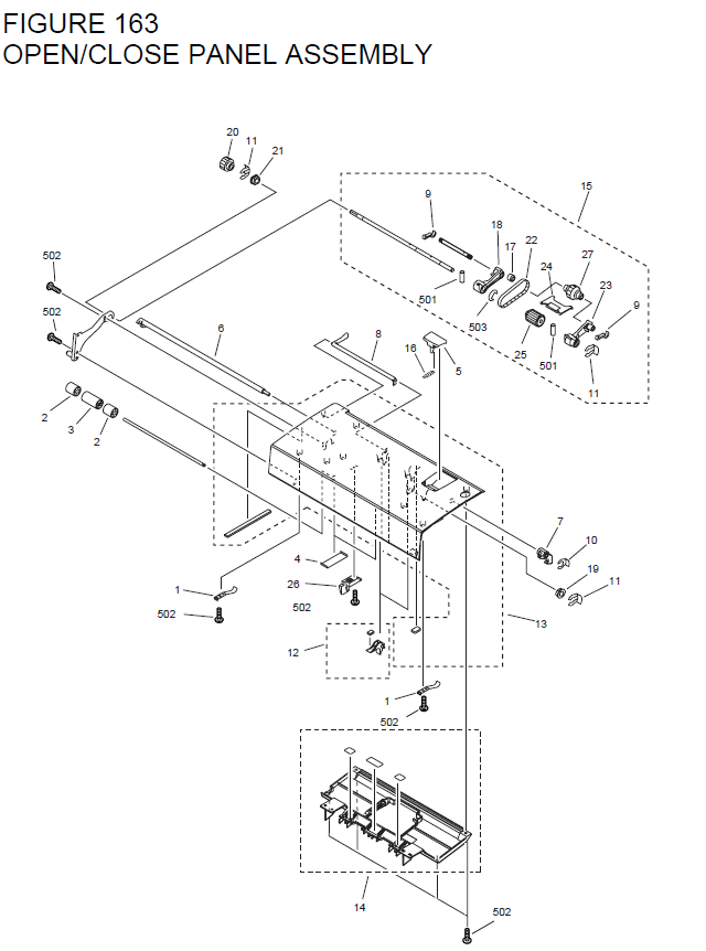
Connect the output of a Power module. Apr 12, · Wiring Diagram and other info can be found on my BLOG schematron.org This video goes over the wiring diagram and pinout for all the components for a PixHawk Lite airplane setup. Pixhawk Wiring Quick Start.
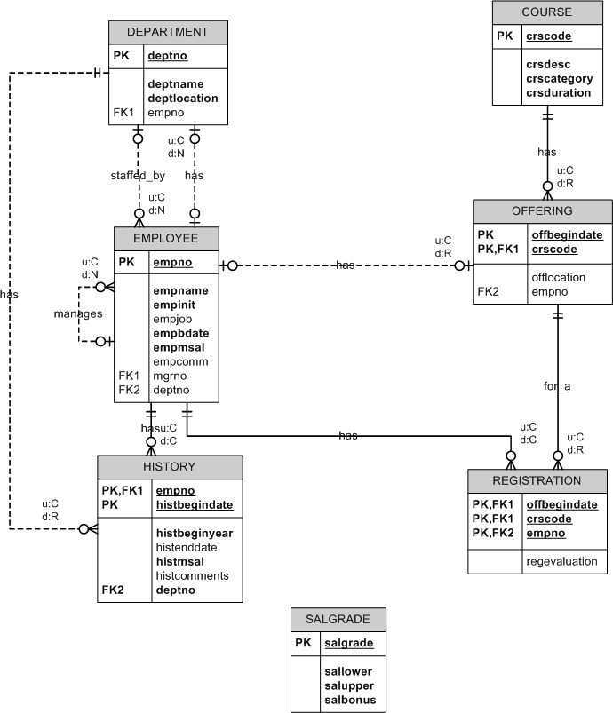
The diagram shows a combined GPS and Compass. The GPS/Compass should be mounted on the frame as far away from other electronics as possible, with the direction marker towards the front of the vehicle (separating the compass from other electronics will reduce interference). Connect the output of a Power module.How to setup APM/PixHawk telemetry correctly? – RC GroupsWiring diagram minimosd, VTX, 3DR Telemetry, GoPro, PX4
