WIRING. Suite/Apartment Stations.
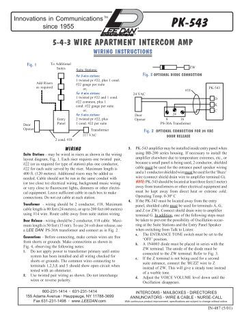
Stations may be connected in risers using the cable configurations as per Figure 1—PKA Wiring Diagram. Observe the. Installation Instructions and Wiring for Tek-ENTRY®.
Apartment Entry Systems with PK Amplifier. IL Section A. Rev.
17 – 09/ APPLICATION. schematron.org: LEE DAN PKA WIRE APARTMENT INTERCOM AMOCAM Video Intercom Entry System, Wired 7″ LCD Monitor Video Door Phone.

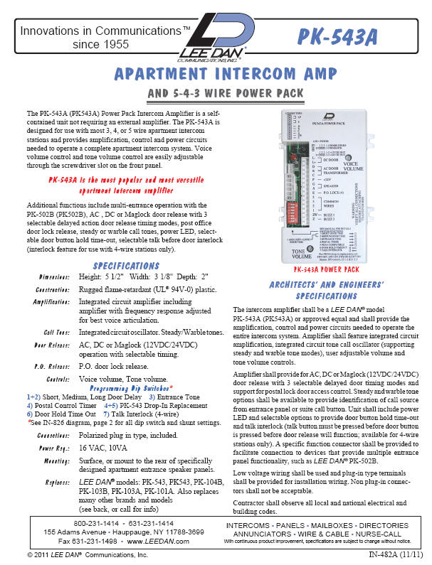
The PKA Power Pack Intercom Amplifier is a self contained unit not requiring an external amplifier. For 5-wire, 4-wire, For WIRING DIAGRAM Click Below.
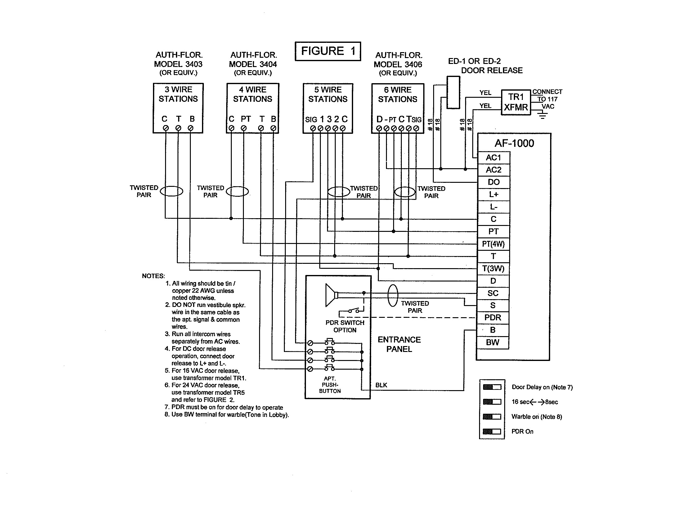
Make connections as shown on the wiring diagram for the amplifier being used. ( For PK/A amplifier, refer to Figure 1, Figure 2 and Figure 3. For PKThe PK is designed for use with 3, 4 or 5 wire apartment speaker type stations and provides amplification, control and power circuits needed to operate a complete apartment intercom system.
Voice volume control and tone volume control are easily adjustable through the . WIRING Suite Stations – may be wired in risers as shown in the wiring layout diagram, Fig.
1. Each riser requires one twisted pair, #22 (or as required for type of station) plus one conductor.
diagram, or Figure 1 (page 4) for wiring/hook-up diagram. Entrance/Lobby Panel Locate the entrance panel where it is sheltered from weather.
If it must be mounted outdoors, consider wind direction and optional Rain-Guard weather hood. PKA Amplifier Install amplifier inside the entrance panel if space.
PKA Tektone Intercom Ampilfier Wiring Diagram. PKA Tektone apartment intercom entry system control amplifier. Designed for use with 3-, 4- or 5-wire apartment remote stations providing amplification, control and power circuits needed to operate a complete apartment intercom entry system.
Figure 2—LIB Wiring Diagram for PKA Systems (Refer to IL for system wiring details) must be used in conjunction with the PKA Amplifier to supply power to the strobes. The LIB Strobe trigger (buzz) is typically sourced by the same tone line that feeds the remote station (X terminal). This tone signal is approx -.Pacific Electronics 6-Wire Plastic Intercom StationAlpha Communications™ MULTI-ENTRANCE ADAPTERAUDIO
