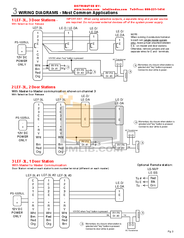
Operation and installation instructions for the PMS3 Power Management System Installation & User Instructions PMS3V/H Fig 2 – Wiring Diagram Installation.

Hi We just bought a 20 year old Mazda Bongo. It has a PMS3 power management system.
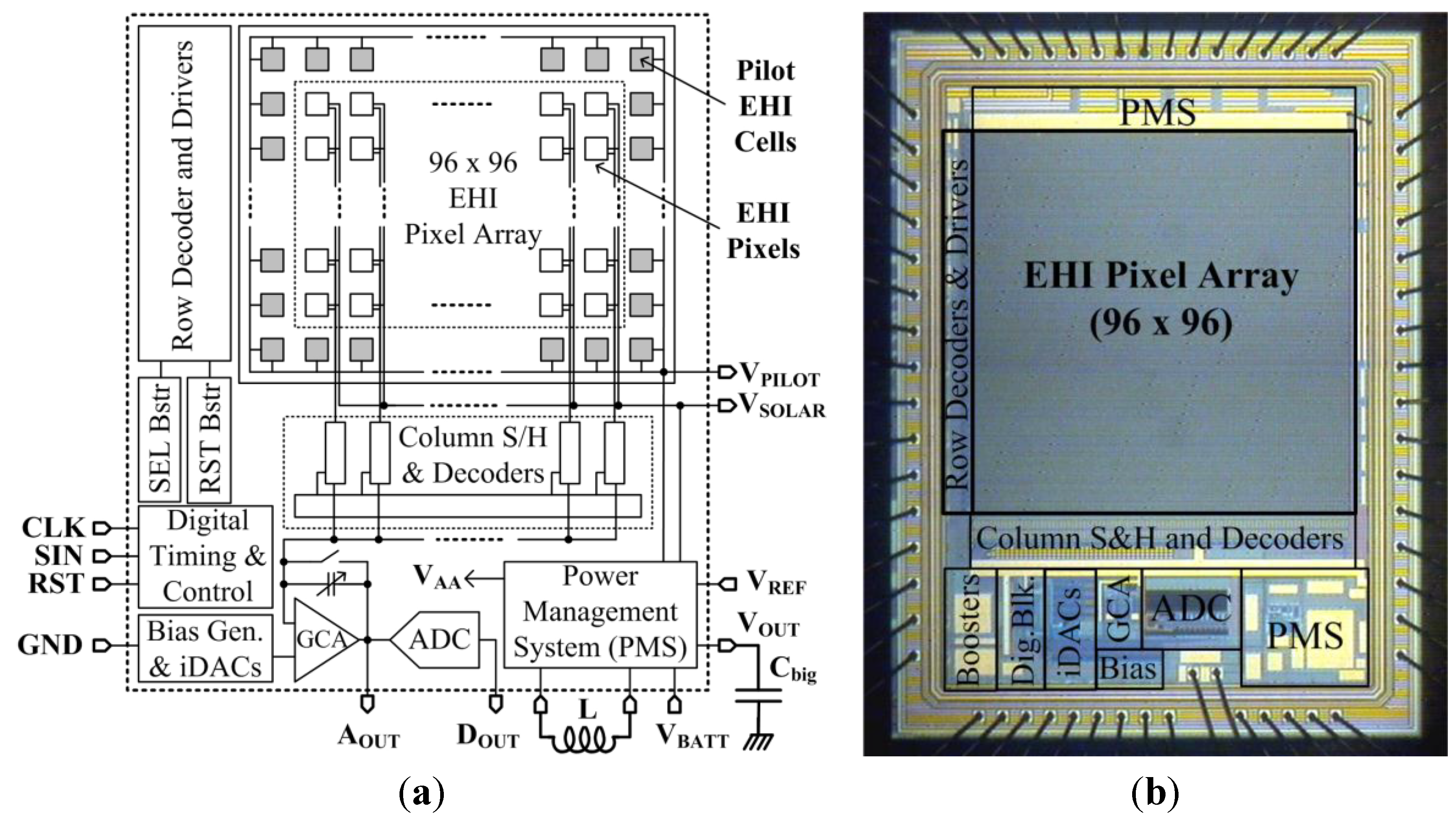
I’ve found the manual online and read various forum. power management system pms 3vMotorhomes and Campervans.
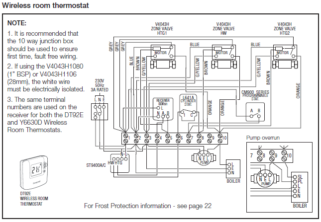
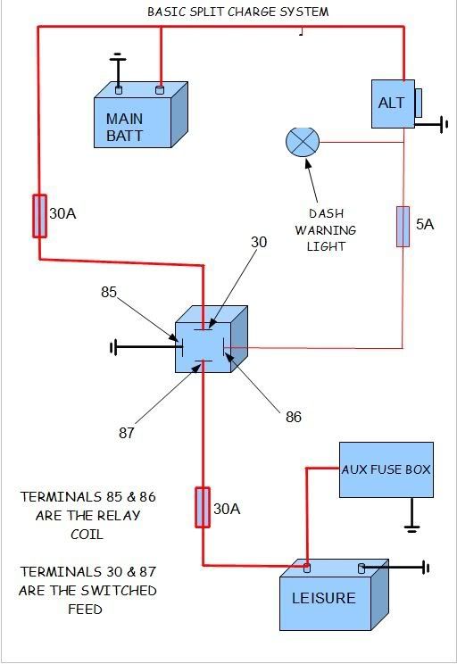
I was supplied a wiring diagram from Bonus and it shows that to charge. power management system pms 3vMotorhomes and Campervans. I was supplied a wiring diagram from Bonus and it shows that to charge. Hi We just bought a 20 year old Mazda Bongo.
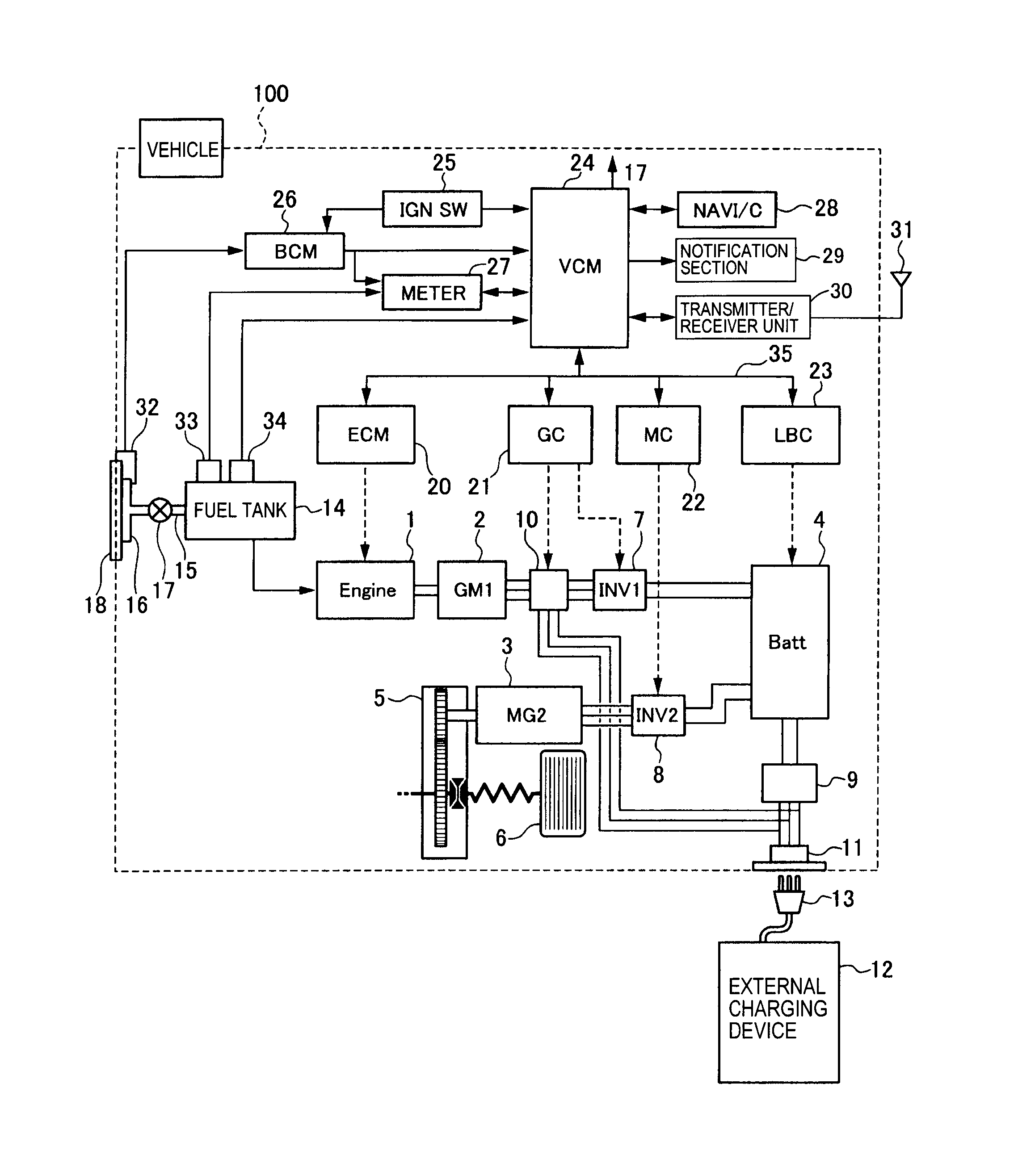
It has a PMS3 power management system. I’ve found the manual online and read various forum.3.
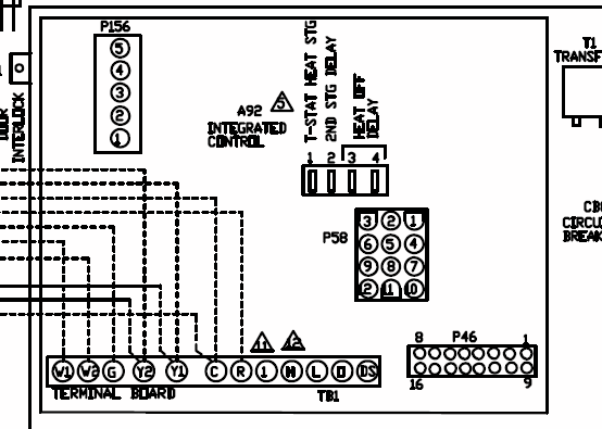
Refer to appropriate wiring diagram. Connect unit to ballast and lamp leads per wiring diagram.
Note: A 7/8″ dia. conduit entry hole may be required to access lamp/ ballast and AC power wires.
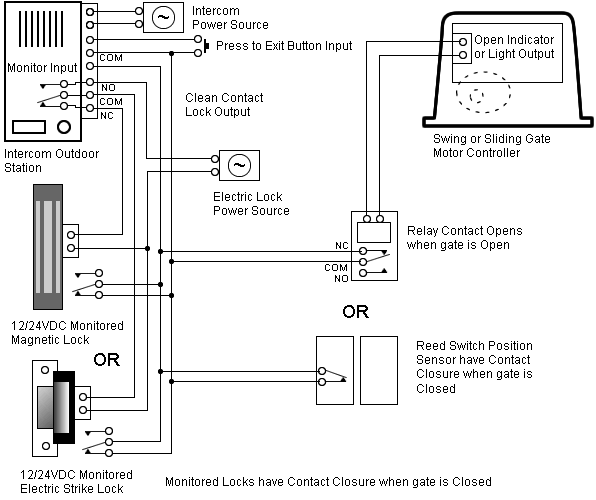
INVERTER INSTALLATION AND WIRING 2. Feed PSDL3 flex conduit through corresponding hole in external wireway cover.
Attach appropriate. Pms3 Instructions – Download as PDF File .pdf), Text File .txt) or read online.
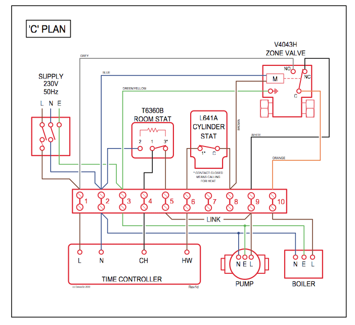
The PMS3 Power Management System is a Volt AC mains and 12 The unit can now be electrically connected using the Wiring Diagram (See Fig 2). Check in-line battery fuse has not blown. Place the CHARGER SUPPLY switch to the ON position.
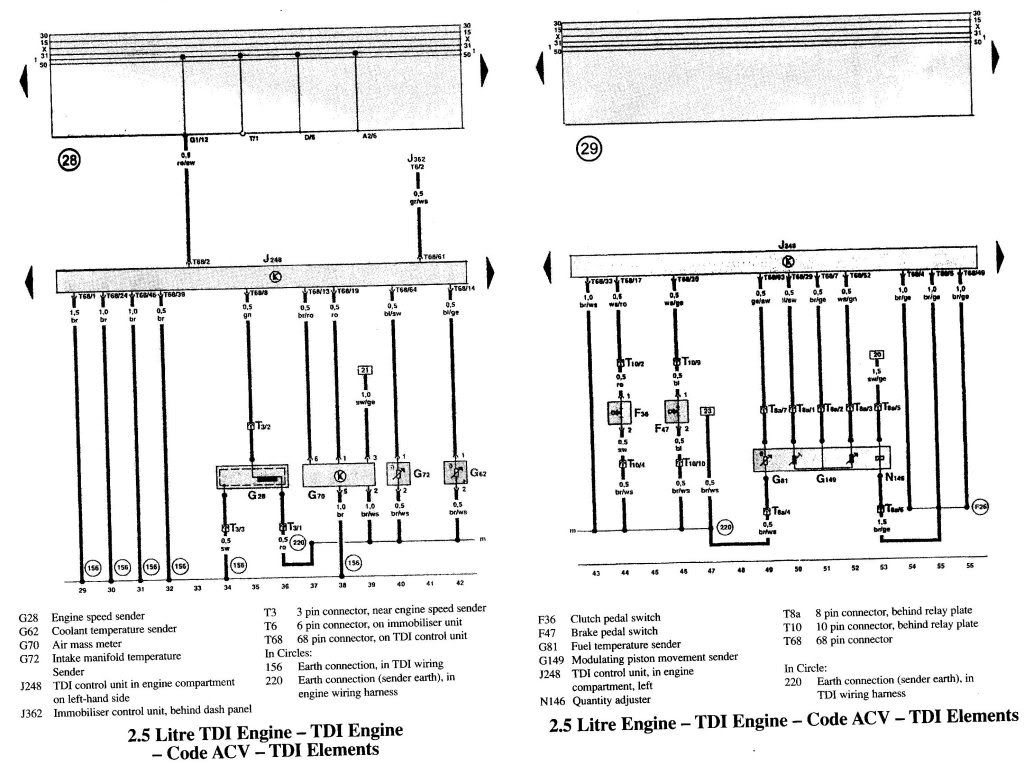
UK Caravanning (schematron.orgnning) A forum for the discussion of caravanning undertaken by residents of the United Kingdom, whether in the UK or abroad. It encourages the interchange of views on the merits of models of caravan, makes of tow car, accessories, .
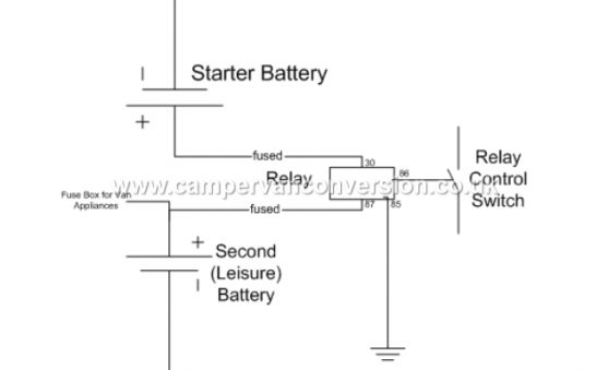
The PMS 3 is designed to work with a battery in circuit, 5 The unit can now be electrically connected using the Wiring Diagram (See Fig 2). Ensure that the correct cable is used at all Installation & User Instructions 3/3 hb schematron.org Fig 2 – Wiring Diagram.
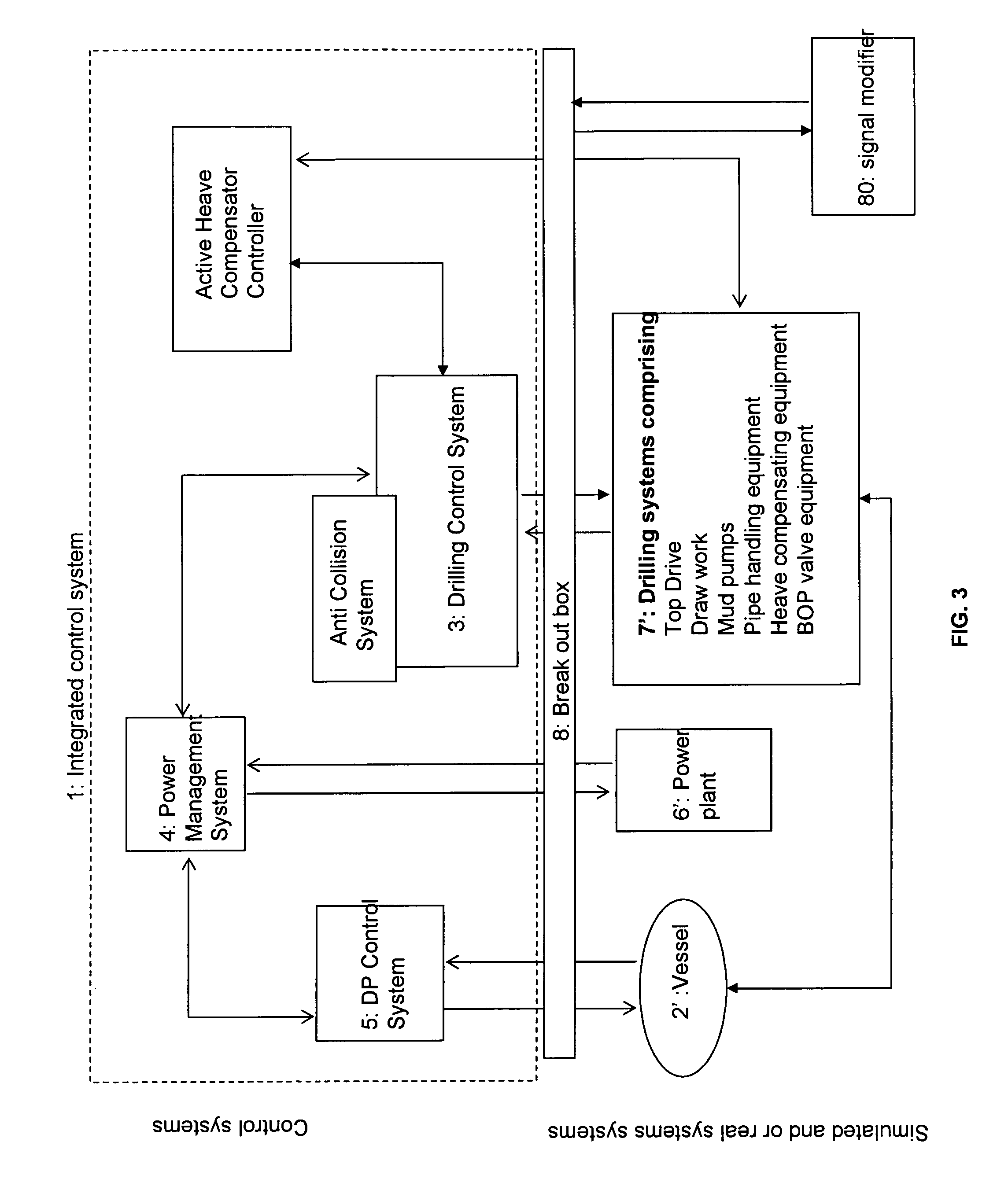
Title: Overview Author: schematron.org Installation wiring diagrams are provided for reference and cover motorhome and caravan installations. You should use wiring of an appropriate cross sectional area to suit the circuit design.
V and 12V wiring should be ran separately and never clipped or tied together.Plug-In Systems PMS 3 – queries | Motorhome Matters | Motorhomes ForumPMS3 Full System Wiring Diagram – VW T4 Forum – VW T5 Forum