Pilz PNOZ s5 24VDC 2 n/o 2 n/o t manuals and user guides for free.
Read online or download in PDF without registration. Connection of CET3-AR to safety relay PNOZ s5.
Content. Guard locking Principle circuit diagram.
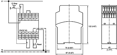
Automatic, manual start – without short circuit detection. Pilz PNOZ s5 24VDC 2 n/o 2 n/o t manuals and user guides for free.
Read online or download in PDF without registration. PNOZmulti: The safety circuit is created using a simple ..
bar chart. To do this the architecture of the. SRP/CL in divided into categories.
MTTFD .. PNOZ s5.
– Safe standstill of one drive. PL e of EN ISO ,.
SIL 3 of EN PNOZ s5. EN Timing diagram.
][ Zeitdagrm_PNOZsautomnebr12SmidlAnauf. Key. ▻ Power: Supply voltage.

▻ Reset/Start: Reset circuit.Sep 20, · Quick clip showing the wiring of Pilz Safety Relays within our controls panel. The Pilz Safety Relays that are shown are the Pilz PNOZ S3 and Pilz PNOZ S11 types and were supplied as .
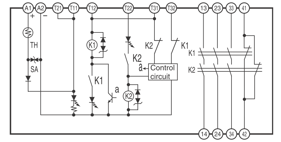
E-STOP relays, safety gate monitors Pilz GmbH & Co. KG, Felix-Wankel-Straße 2, Ostfildern, Germany Block diagram PNOZ X5 Wiring Please note: `Information given in the “Technical details” must be followed.
Pilz Pnoz Xv2 Wiring Diagram
PNOZ XV1P NSG-D Terminal configuration Klemenbgu Installation MontageMontage_PNOZ_X` The safety relay should be installed in a control cabinet with a protec-tion type of at least IP `Use the notch on the rear of the unit to attach it to a DIN rail. `Ensure the unit is mounted securely on a vertical DIN rail (35 mm) by us-.
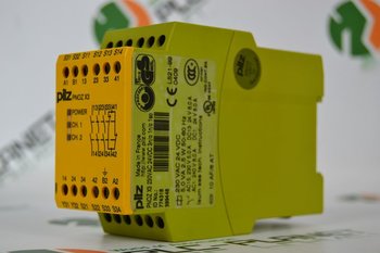
E-STOP relays, safety gate monitors Pilz GmbH & Co. KG, Felix-Wankel-Straße 2, Ostfildern, Germany Up to PL e of EN ISO PNOZ XP NSG-D Gertebild][schematron.org_LichtSafety relay for monitoring E-STOP pushbuttons, safety gates and light beam devices Block diagram Blockshaltbild *only. PNOZ s5 Operating Manual PNOZ s5 EN 4} Plug-in connection terminals (either spring-loaded terminal or screw terminal) Safety features The relay meets the following safety requirements:} The circuit is redundant with built-in self-monitoring.} The safety function remains effective in the case of a component failure.Circuit Diagrams of Safety Components | Technical Guide | Australia | Omron IAPnoz S4 Wiring Diagram – Wiring Diagram And Fuse Box
