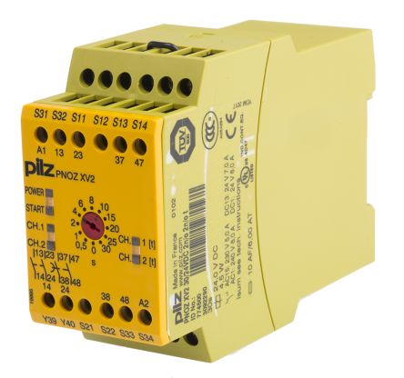
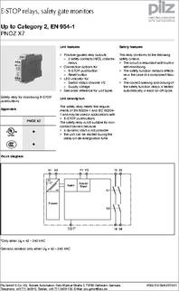
Buy PILZ PNOZ X7 24VAC/DC online at Newark element safety contacts (N/ O), instantaneous; Connection options for E-STOP pushbutton and reset button.
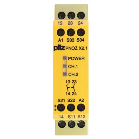
PNOZ X7. NSG-D Safety relay for monitoring E-STOP pushbuttons. Block diagram.
*Only when Manual reset: Unit is active once the input. Automatic reset.
○ Manual reset. Emergency Stop Relays, Safety Gate Monitors.
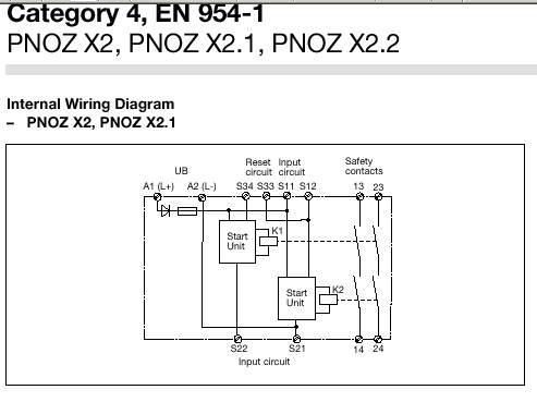
Category 2, EN PNOZ X7 24 V DC/AC, PNOZ X7 AC. PNOZ X7.
○. ○.
Contents. Operating Manual PNOZ X7.
EN 3. Introduction.
4. Validity of documentation. 4.
Using the documentation. 4.

Definition of symbols. 4.
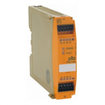
Safety. Buy Pilz 24 V ac/dc Safety Relay Single Channel with 2 Safety Contacts Compatible With Safety Automatic and manual reset facilities available with the X7.The safety relays PNOZ monitor safety functions such as E-STOP, safety gates, light barriers, light grids, two-hand controls, pressure sensitive mats, speed, standstill and much more schematron.org day, PNOZ safety relays prove themselves in millions of applications worldwide.
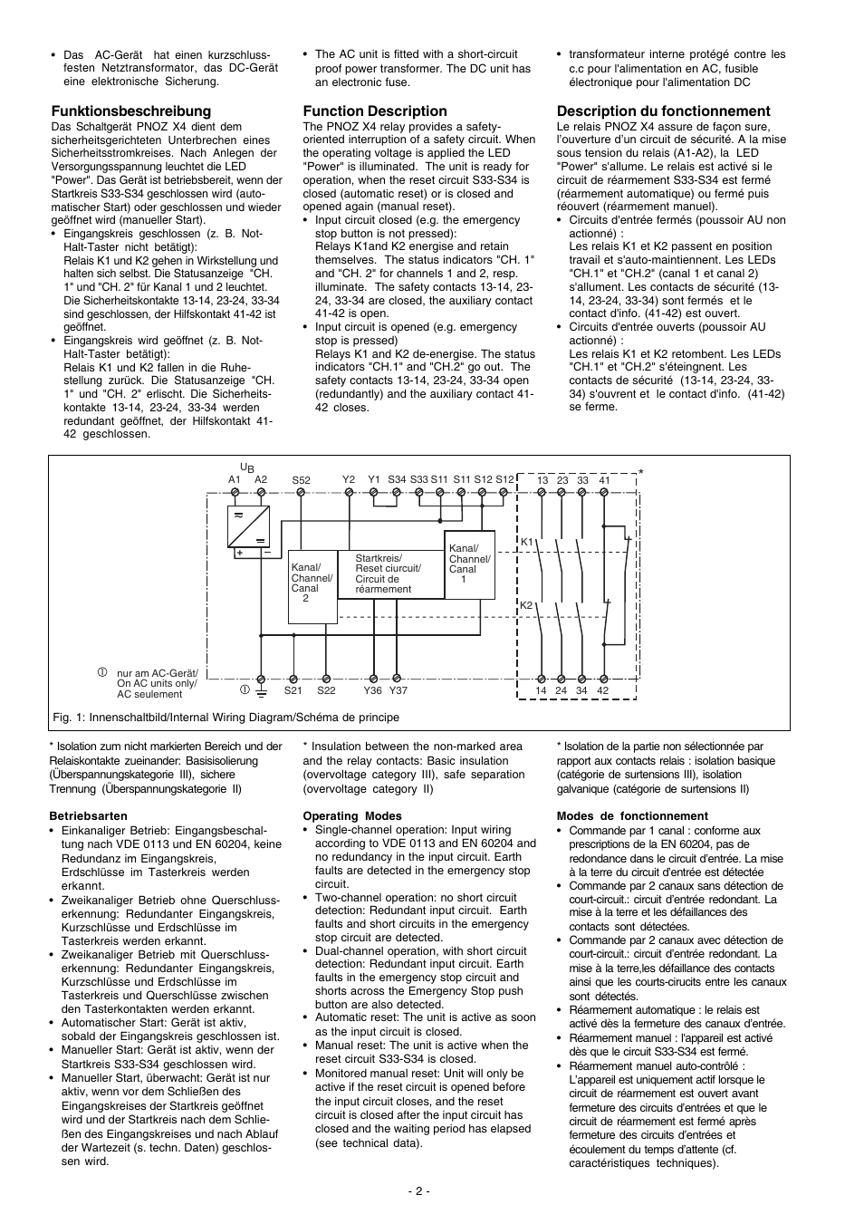
In Pilz patented the first emergency stop relay to protect man and machine. Emergency Stop Relays, Safety Gate Monitors Category 3, EN PNOZ 3 Internal Wiring Diagram External Wiring Example 1 Single-channel E-STOP wiring with manual reset.
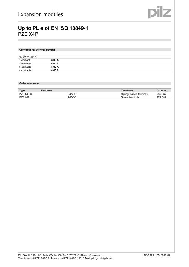
Example 2 Dual-channel E-STOP wiring with manual reset. T11 T12 T33 T12 X1 T22 T34 X2 S1 S3 Increase in safety contacts The number of output contacts can be increased by using.
Pilz Pnoz X7 Wiring Diagram
The PNOZ X7 Series from Pilz are safety relay for monitoring E-STOP pushbuttons. The safety relay meets the requirements of EN and IEC and may be used in applications with E-STOP pushbuttons.
The safety relay is not suitable for noncontact barriers because a dynamic start is not. Emergency Stop Relays, Safety Gate Monitors Category 4, EN PNOZ X3 Internal Wiring Diagram A1 A2 S13S14 S12 S21 S34 41 42 S11 S22 S31 S32 13 33 14 34 K1 K2 23 24 & Y32 Y31 CH2 Start CH1 Unit S33 AC DC B1 B2 +-UB Reset circuit Input circuit Safety contacts Auxiliary contact Input circuit External Wiring Example 1 Single-channel E-STOP. PNOZ X Safety Relays Application Manual – Pilz | Brochures.Safety relay PNOZ X – Emergency stop, safety gate, light grids – Technical features – Pilz GBSafety relays – Pilz GB
