I am getting an error code (crankshaft position sensor faulty)on my Ranger Crew Will turn over but will not crank.
On this post. Polaris RANGER XP EU (R15RTE87FA) OEM Parts. Polaris Electrical, Turn Signals, Horn And Mirrors · Engine Engine, Crankshaft & Piston .
Buy OEM Parts for Polaris Side by Side Electrical, Sensors & Modules All Options Diagram. Polaris · Side By Side · · RANGER XP ALL OPTIONS – R16RT_87; Electrical, Sensors & Modules All Options.
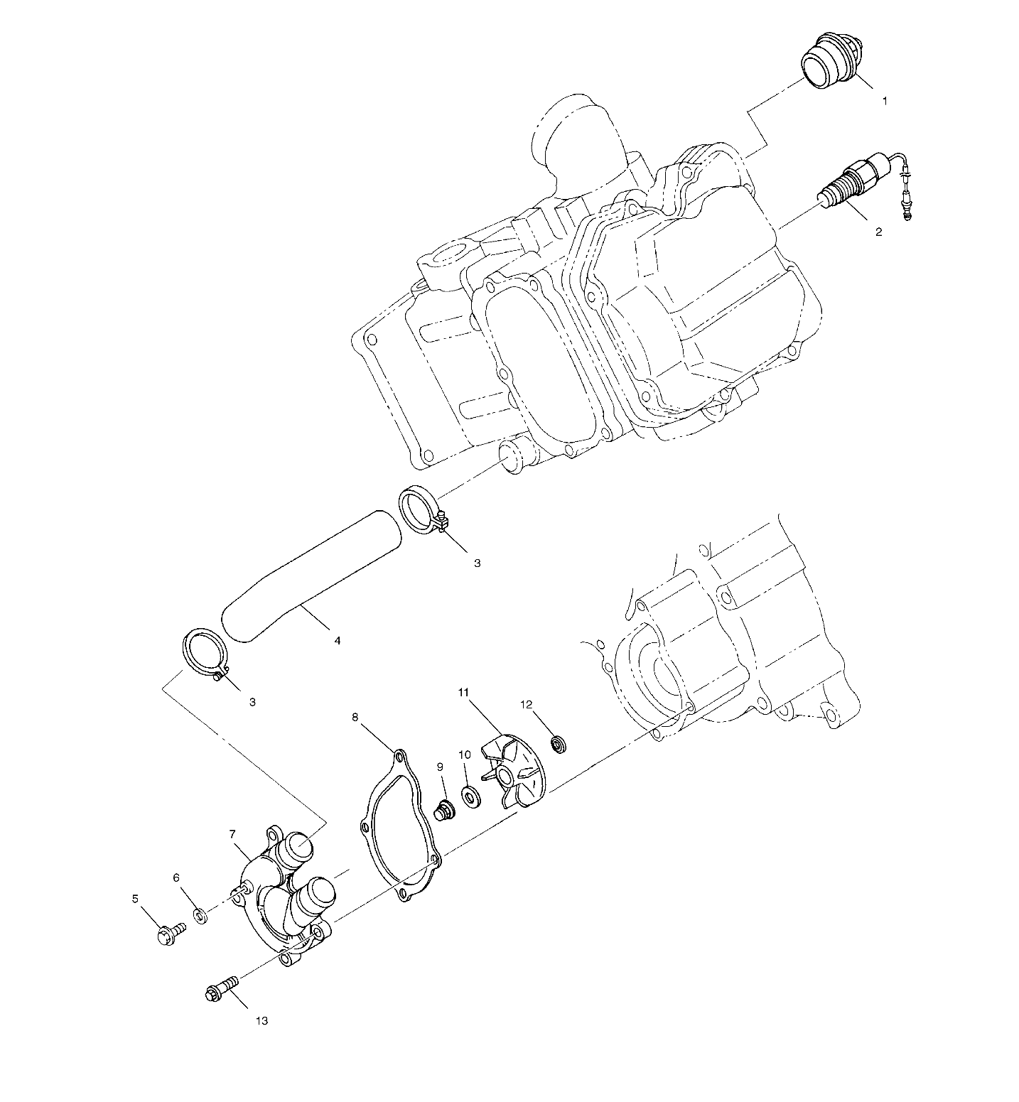
Check Availability. Select your address. #, Description, Price, Qty.
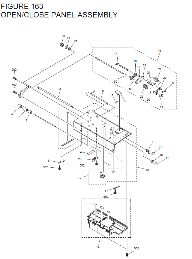
1, SENSOR, CRANK POSITION. Results 1 – 48 of Thermostat For Polaris Ranger Crew Ranger XP RZR Sportsman . CRANK POSITION SPEED SENSOR FITS Polaris RANGER CREW ..
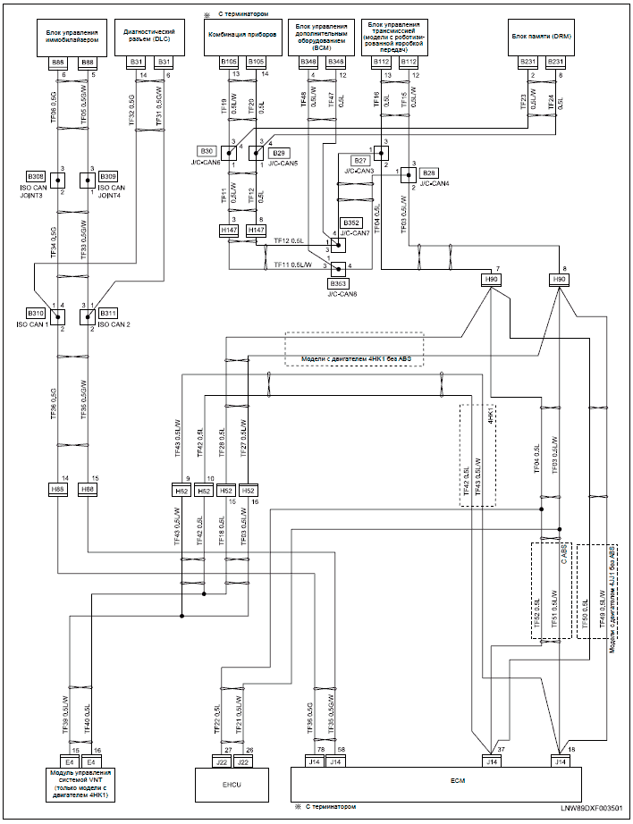
Wiring diagram for horn / turn signal kit included!. This Service Manual is designed primarily for use by certified Polaris Master Service Dealer® – RANGER RZR XP Service Manual The engine serial number can be found on a decal applied to the crankcase, on the front ..

Maintenance intervals in the following chart are based upon average riding.A Battery Connection Cable is a necessary component to connect your accessory busbar to the vehicle battery when installing Winches, Audio Systems or Lighting. Perfectly fit to your vehicle, wires are cut to the precise length for your vehicle to minimize slack.
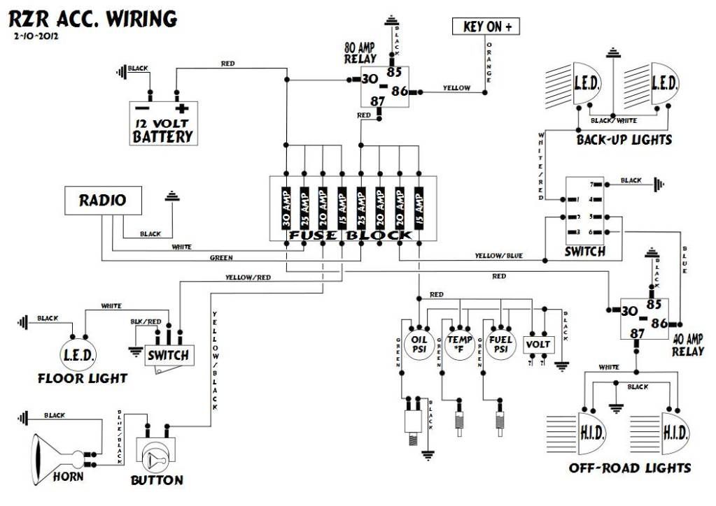
Polaris Sensor – Crank Position () is used in Electrical, Sensors assembly for Polaris RZR EFI, Sensors and Modules – R13UH88/UH9E All Options assembly for Polaris RANGER XP ALL OPTIONS – R13UH88/UH9E, Switches, Sensors and Ecm – A14MH57AA/AC/AD assembly for Polaris Sportsman EFI, Sensors and Modules – R14UH88/9E/9EAN All Options assembly Brand: Polaris. Oct 11, · Re: Complete wiring diagram Thanks guys got it figured out i dont know how to work everything on here yet.

With the polaris manual had a nice . James from Houston, TX on Tuesday, December 10, Difficulty level: Average 06 Ranger XP gave me a “21” code at the service indicator “wrench” light.
(loss of synchro). After researching it I was told that this was an indication of crankshaft position sensor issues or a wiring problem related to schematron.org: Polaris.
Hall Sensor Probe Harness (PN ) 1. Disconnect wire harness from speed sensor and remove sensor from right front brake caliper mount.
2. Connect the wires from the Static Timing Light Harness to the sensor 3 pin connector using the Hall Sensor Probe Harness (PN ). 3.
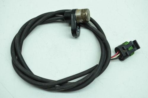
Pass a screwdriver back and forth in front of the sensor tip. 4.KMS PerformancePolaris – Sensor, Crank Position – schematron.org
