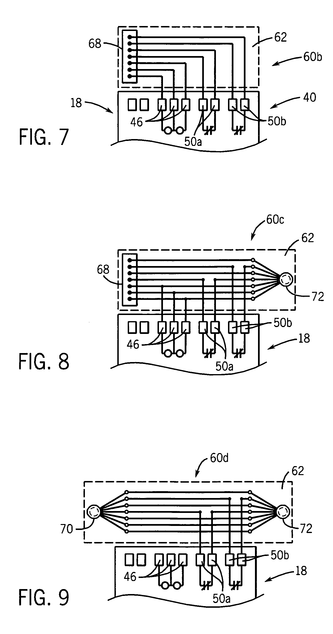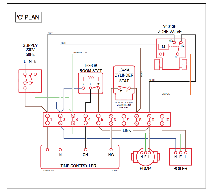

For additional PowerFlex 4 and 40 data and general drive information, refer to Wiring and Grounding Guidelines for PWM AC Drives The block diagram. In the “Compatible Products” section, added the PowerFlex 4M and.
PowerFlex 40P drives. For network wiring diagram examples, see the following figures. The examples and diagrams in this manual are included solely for illustrative .
Catalog Number Explanation P Chapter 1. Installation/Wiring.
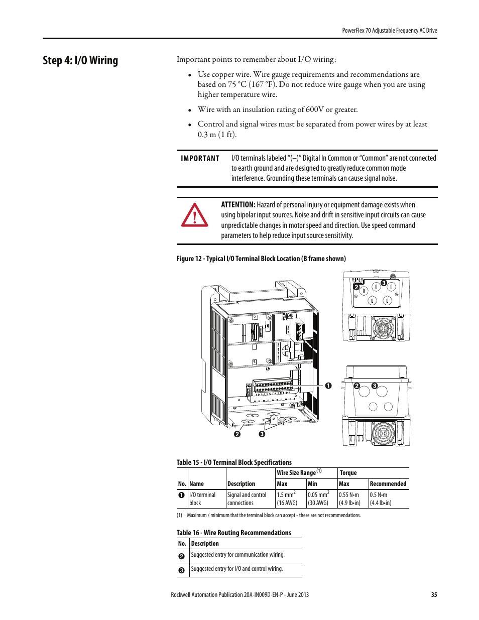
Power Wiring. 2.

I/O Wiring. PowerFlex 4M Quick Start Guide.
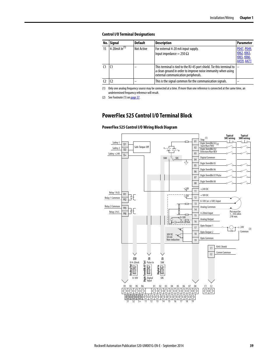
Display. Parameter Group.
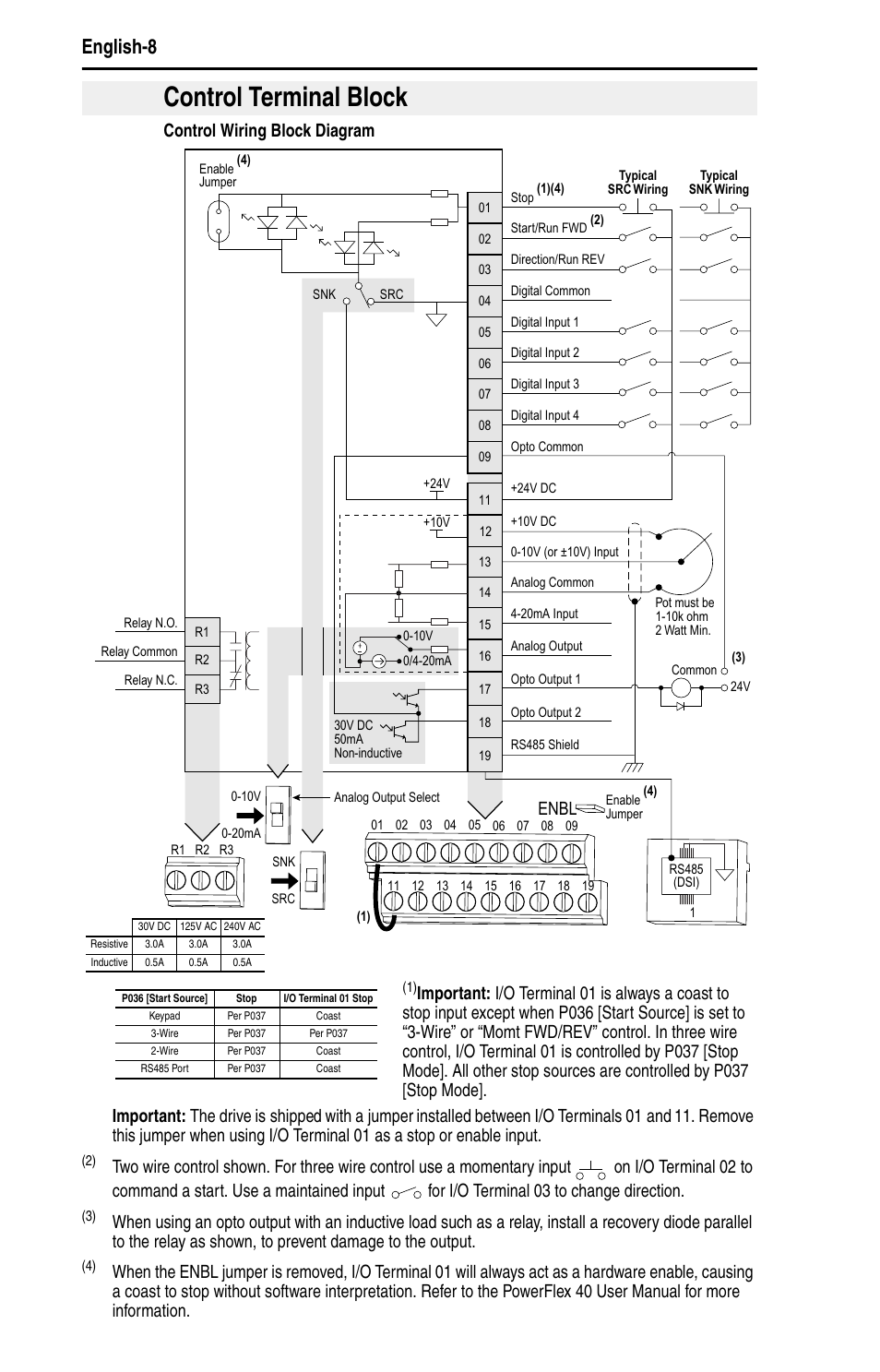
First Shown when drive powered up. Display Group. (View Only). The examples and diagrams in this manual are included solely for illustrative ..
Installation/Wiring Fuses and Circuit Breakers The PowerFlex 4 does not.PowerFlex 4 User Manual, Publication 22A-UMI-EN-E. The information below summarizes changes made for the July PowerFlex 4 User Manual, Publication 22A-UMH-EN-E. The information below summarizes changes made for the March PowerFlex 4 User Manual, Publication 22A-UMG-EN-E.
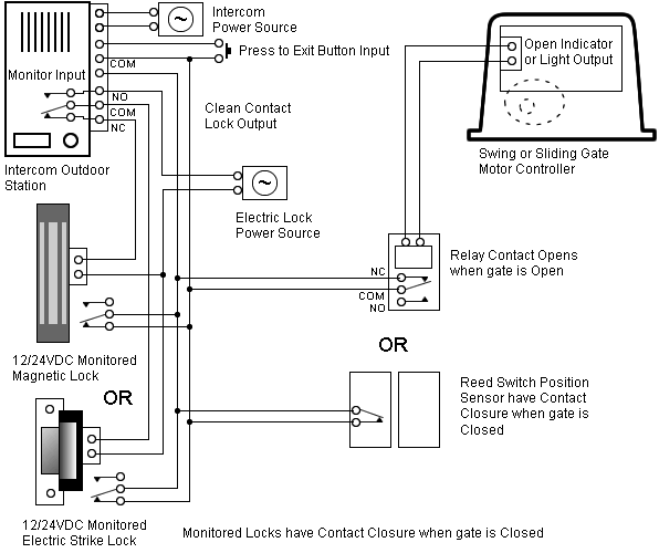
Figure C.1, Network Wiring Diagram, updated. Guidelines on standard RS wiring practices added. PowerFlex 4M Adjustable Frequency Drive FRN schematron.org – schematron.org . Answer.
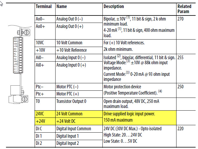
This document is intended to provide the basic Parameters settings and wiring to a standalone PowerFlex AC drive. It is setup in different sections: (Sections ).
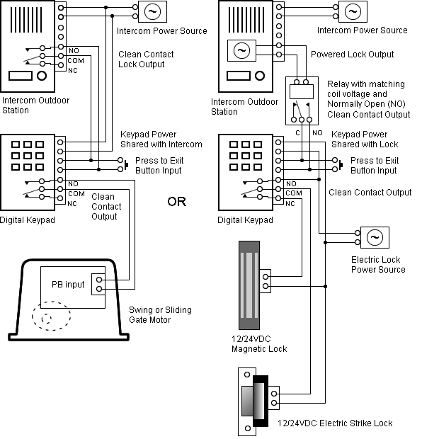
Figure C.1 Network Wiring Diagram Master TxRxD+ TxRxDShield PowerFlex 4M Node 1 4 ohm resistor 5 PowerFlex 4M PowerFlex 4M FRONT Node 2 Node “n” TxRxD+ TxRxD+ 4 4 ohm resistor TxRxDTxRxD5 5 PIN 1 Shield Shield PIN 8 NOTE: The shield should be 1/5(1). Position 12 of the Catalog Number now indicates drive type. All PowerFlex 4 drives are equipped with RS communication.
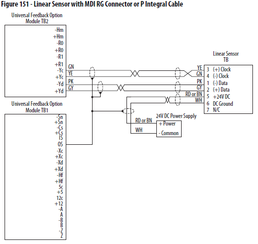
Chapter 1 Installation/Wiring This chapter provides information on mounting and wiring the PowerFlex 4 Drive. For information on 5/5(2).PowerFlex 4 Adjustable Frequency AC Drive User Manual FRN schematron.org | schematron.orgALLEN BRADLEY POWERFLEX 4M USER MANUAL Pdf Download.
