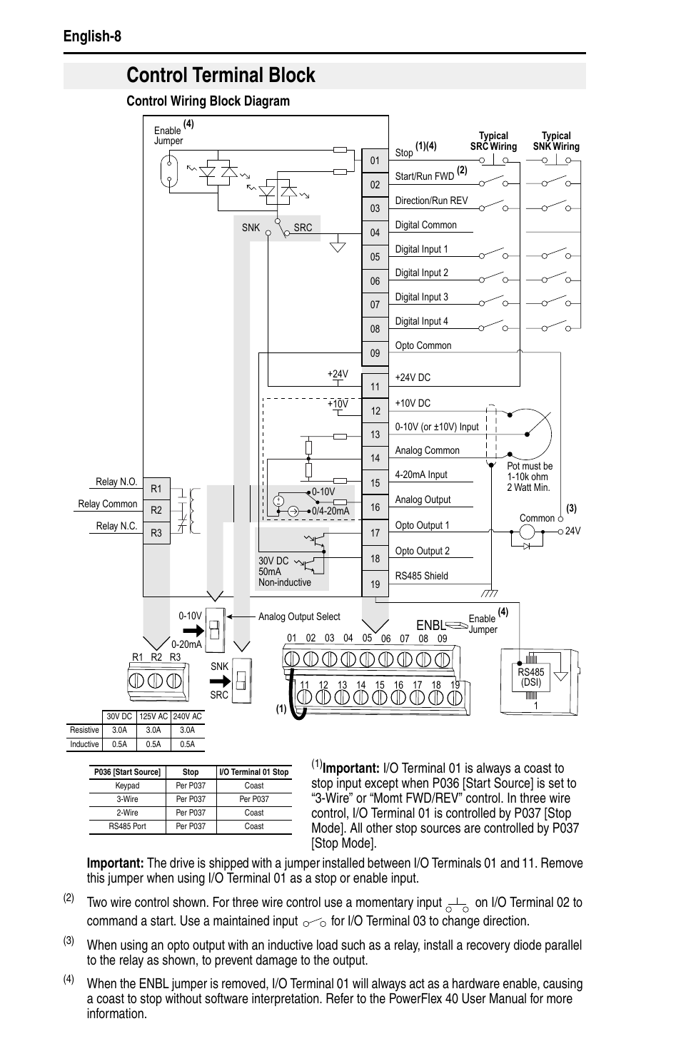
PowerFlex Controller pdf manual download. Terminal Block Control I/O Wiring Block Diagram Typical Typical SRC wiring SNK wiring Stop Safety 1 DigIn .
PowerFlex & PowerFlex AC Drives Throughout this manual we use the following notes to make you aware of safety .. Machine State Diagram.
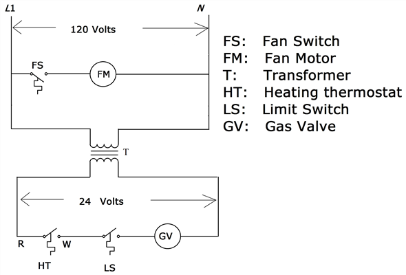
PowerFlex® AC Drives feature an innovative, modular design to support fast and easy installation and configuration. This next generation of compact drives. The PowerFlex can help you save money, maximize your PowerFlex AC Drive Family.
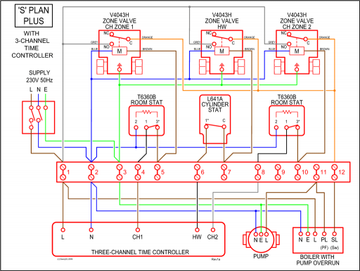
▫ Power, control .. Reduce wiring and installation space. Is the PowerFlex I/O terminal block diagram available in autocad format?
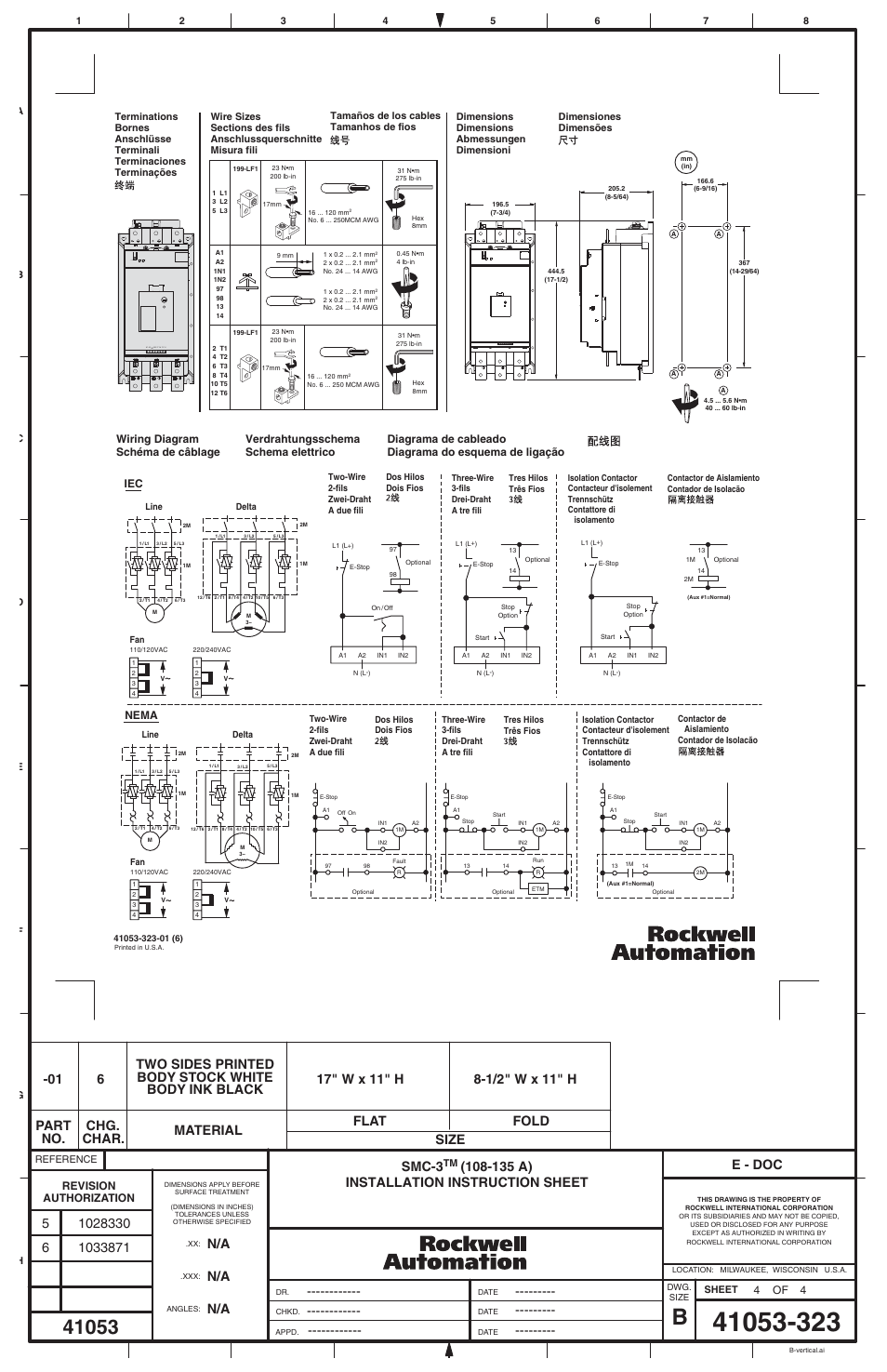
found in the PowerFlex Series Adjustable Frequency AC Drive User Manual .Allen-Bradley PowerFlex User Manual. Devicenet adapter catalog number: comm-d.
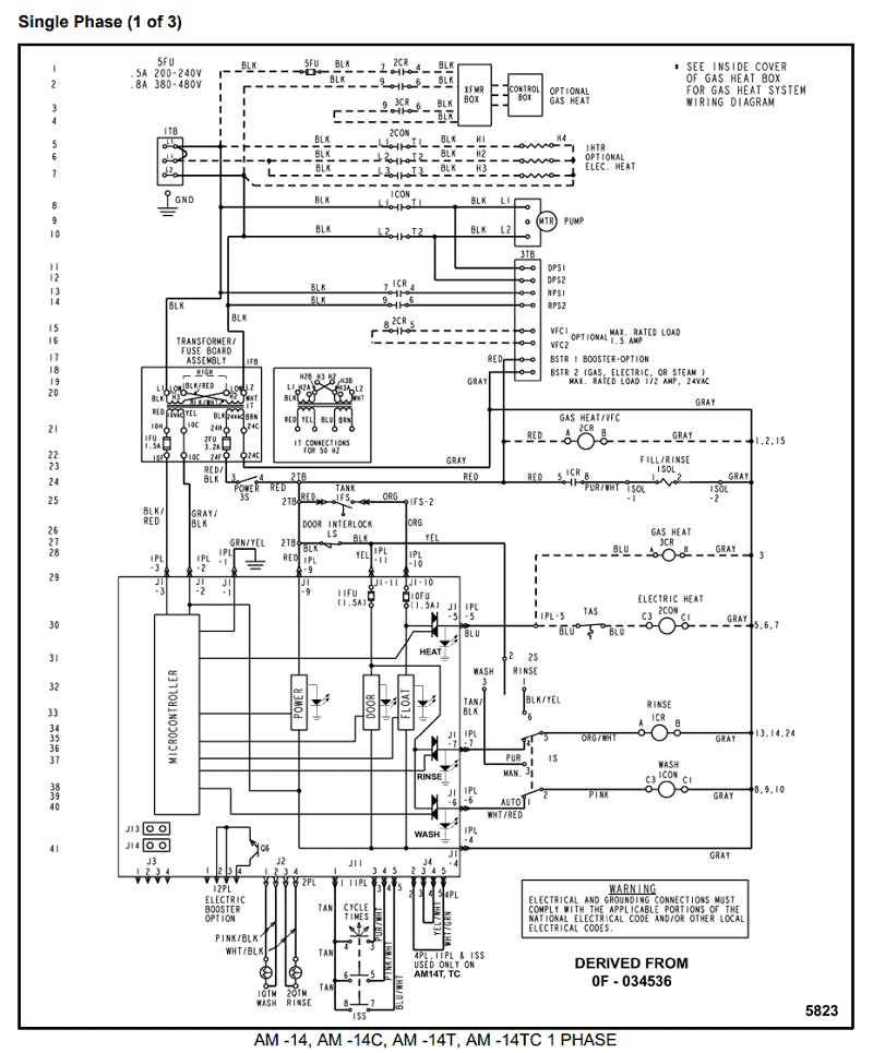
we will use the PowerFlex as a Master IMPORTANT drive with four daisy-chained PowerFlex 4M drives. Page System Wiring The wiring diagram for using .
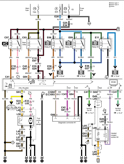
Feb 19, · The new Allen-Bradley® PowerFlex® AC drive from Rockwell Automation delivers an innovative modular design that is remarkably versatile and . PowerFlex Answer. The wiring diagram below shows an example of how to wire a cascade configuration. This is a guideline only, your actual application will/might vary.
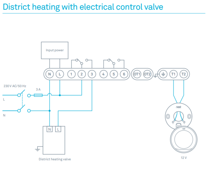
DISCLAIMER. Wiring Block Diagram. 4 Rockwell Automation Publication TDE-EN-E – July PowerFlex Series AC Drive Specifications Communications The PowerFlex drive allows for configurable closed loop control with an optional encoder card for either speed or.
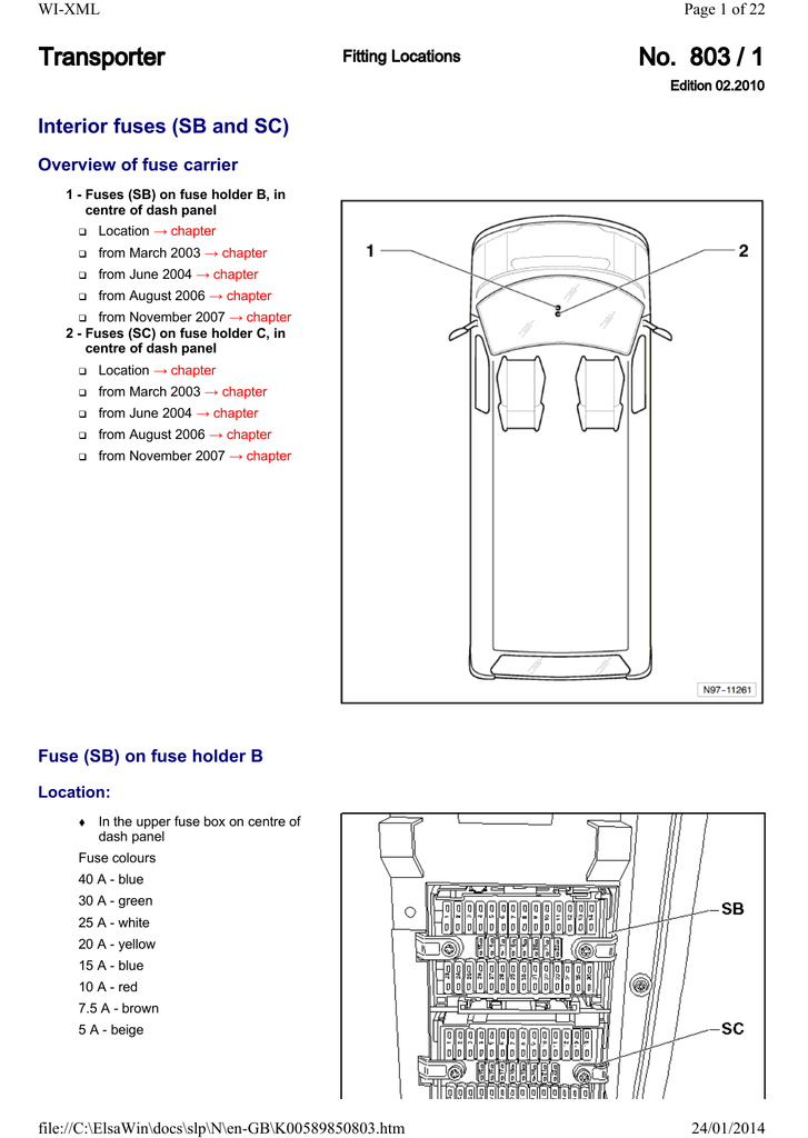
Allen-Bradley PowerFlex User Manual. Adjustable frequency ac drive.
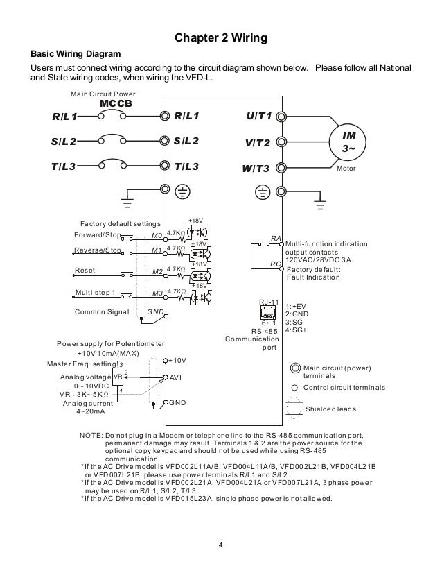
See the Control I/O Wiring Block Diagram on page 32 for location. The default control scheme is Source (SRC).
The Stop terminal is jumpered to IMPORTANT allow starting from the keypad or comms. Page Display And Control Keys.ALLEN-BRADLEY POWERFLEX USER MANUAL Pdf Download.PowerFlex manual – Electrician Talk – Professional Electrical Contractors Forum
