Preamp Vs Power Tube Distortion
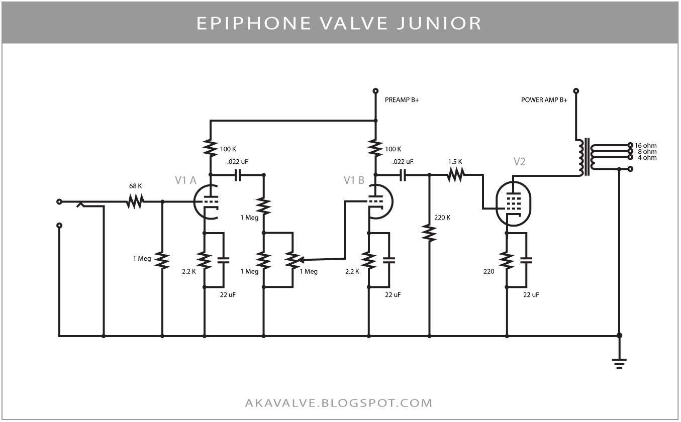
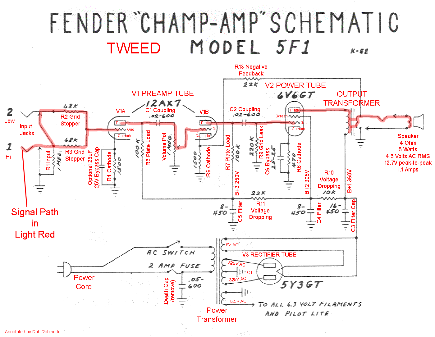
The circuit is a versatile building block anyone can use. This book does not cover tube circuits or unique aspects of guitar amps but is V1a provides an input buffer and gain. In overdrive, V1b provides modest gain and a crunchy sound.
v1, v2, v3??? Preamp positions? Can somebody explain?
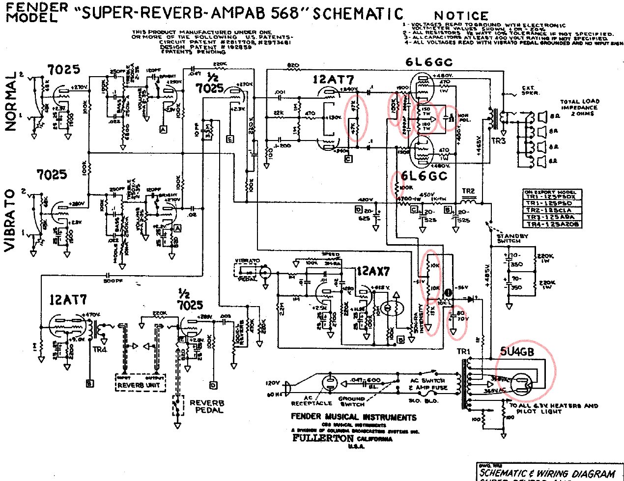
Figure 2 shows the tube-based guitar amplifier’s schematic. I’m thinking of starting to experiment with different preamp tubes.
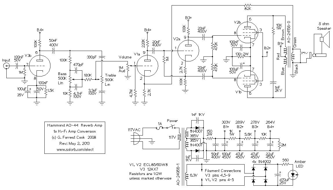
Before I Schematic from input to out labels v1b v1a and v2a. Another part of the circuit may use the other triode of that tube and will be indicated as V1b.
It’s much easier to analyze an amp circuit by studying its schematic than looking at its layout diagram. V1A is one half of tube V1, V1B is the other half. The preamp tube V1 (Valve 1) is made up of two separate triodes called A and B.
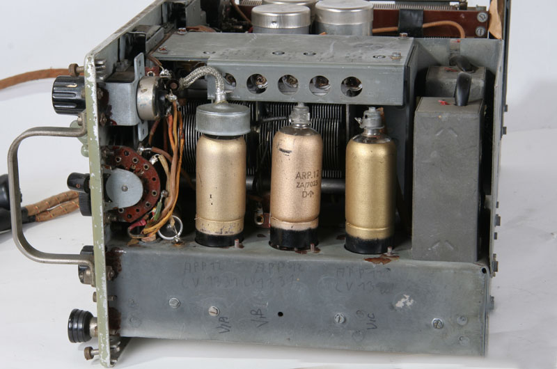
The A. The circuit is a versatile building block anyone can use.
Preamp Tube Substitutions With Steve Carr
This book does not cover tube circuits or unique aspects of guitar amps but is V1a provides an input buffer and gain. In overdrive, V1b provides modest gain and a crunchy sound. Figure 2 shows the tube-based guitar amplifier’s schematic.
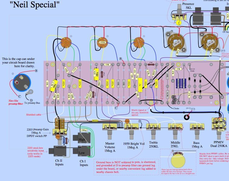
It’s much easier to analyze an amp circuit by studying its schematic than looking at its layout diagram. V1A is one half of tube V1, V1B is the other half.
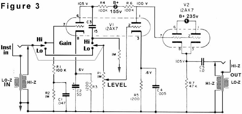
The preamp tube V1 (Valve 1) is made up of two separate triodes called A and B. The A.The following preamplifier wiring diagrams are provided in the event you do not have the original diagram sent with the preamplifier or if you just want an extra copy. If you do not see the wiring diagram you need listed below, please contact Technical Support Department.
.
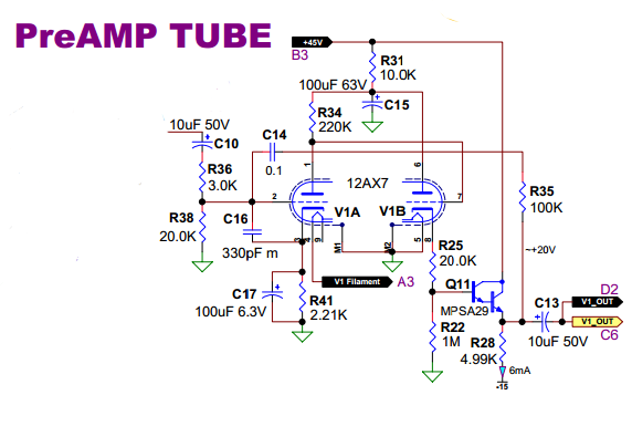
After the Grid Stopper the signal hits Tube V1A’s Control Grid, pin 2 in the schematic above (our 12AY7 preamp tube is actually two tubes in one–a twin triode–and V1A means ‘Valve 1, first triode). V1A is called a triode because it has three electrodes (control grid, cathode and plate, a tube with a fourth, screen grid electrode is called a. Wiring Diagram for Pickup Models: Tone CircuitsTM 2 & 3-Band Active EQ Preamps for Bass STC-2A, STC-2P STC-3A, STC-3P The basic steps for installation include: Proper operation depends on proper hookup of all connections; observe color codes and wire locations carefully.
1. Remove any old pots that will not be used in this new installation.
Vacuum Tube Buffer preamp review and tear down
2. Active preamps and electroinics for guitar & bass from Seymour Duncan & Graphtech. Nov 11, · The is probably the most difficult Marshall to retube.
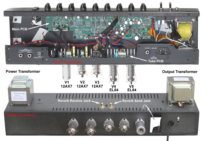
Most people just buy tubes and randomly stick them in. I’m sure the factory didn’t give much thought to it either.
Here is the run down on the tubes. Remember, a 12AX7 has two triodes called A .Explanation of what a Gain Stage is? | Telecaster Guitar Forumpreamp tubes | schematron.org
