DEFROST CONTROLS Adjustable Defrost Initiation Frequency: One to six times per day.
schematron.org Cross Reference. SUPCO.
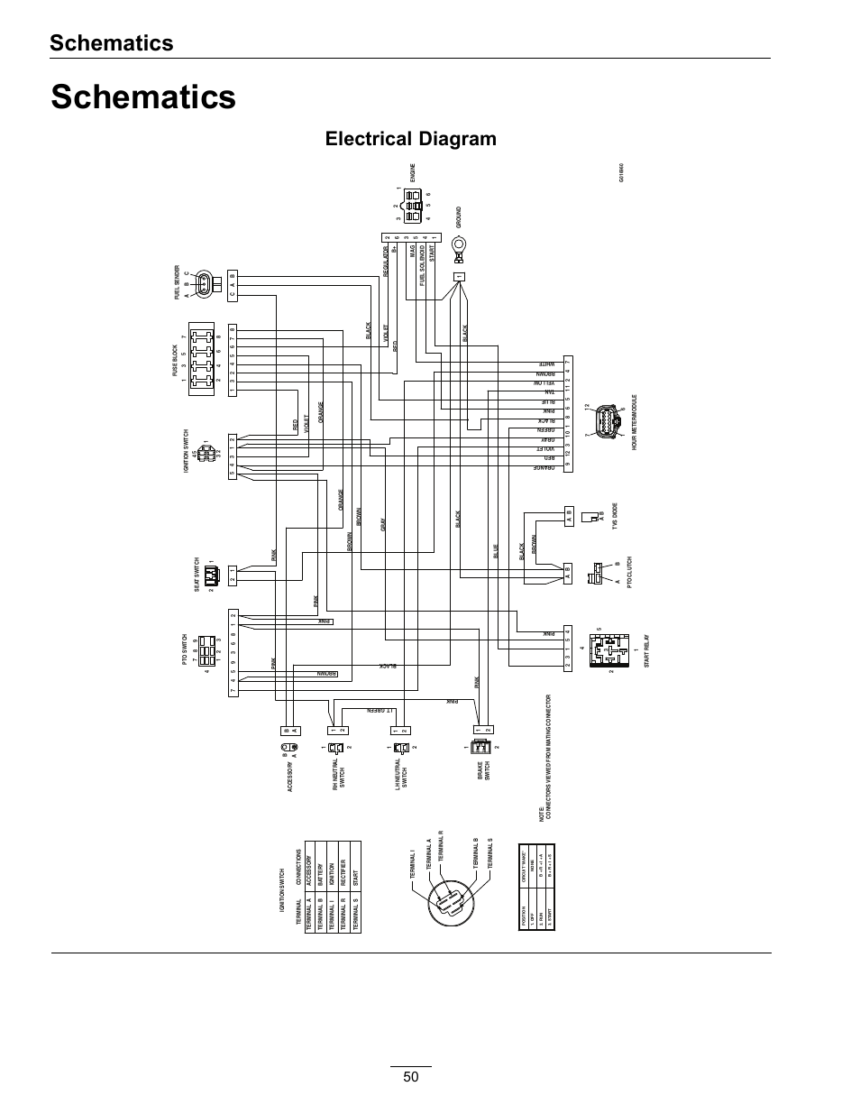
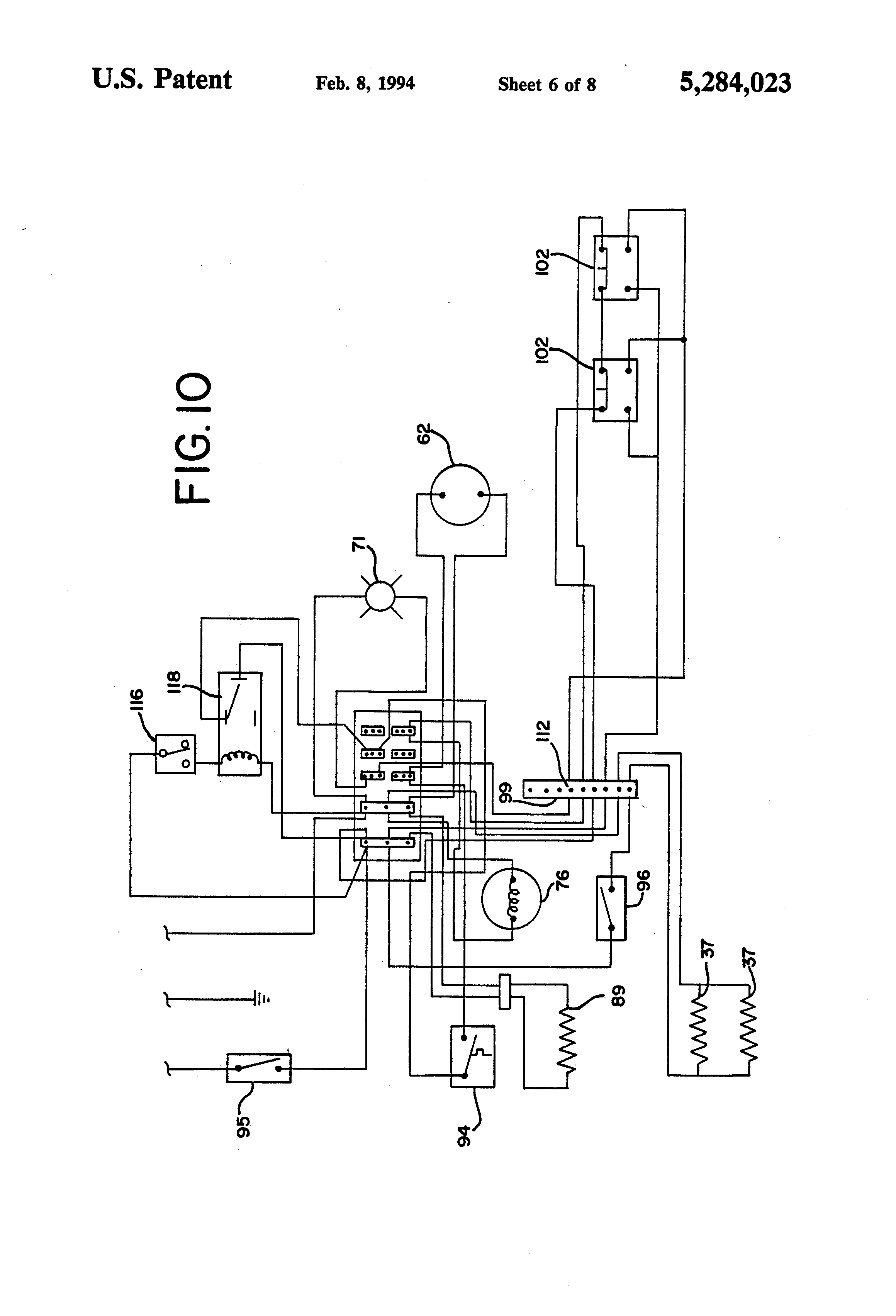
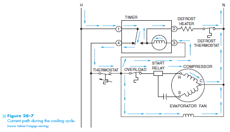
Paragon. Precision. S Wiring Diagrams Electric Heat Defrosting S & S Series.
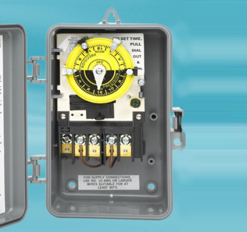
Provides accurate control performance with up to feet of wiring . CONTROLS Operating temperature: 20°F – °F Refrigerant temperature: 35° F Follow the wiring diagram located on the appliance when replacing these controls. Order Number Volts, 60 Hz REFRIGERATION.
F2. Listed The Paragon® Series Auto Voltage Defrost Timer is designed for installation time, and minimizes the number of SKUs to stock. Features Real-time clock face for easy accurate settings.
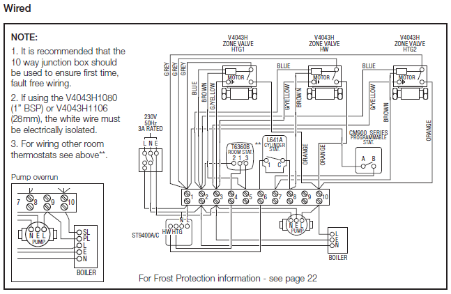
• Defrost S DTAV S . Wiring Diagram.
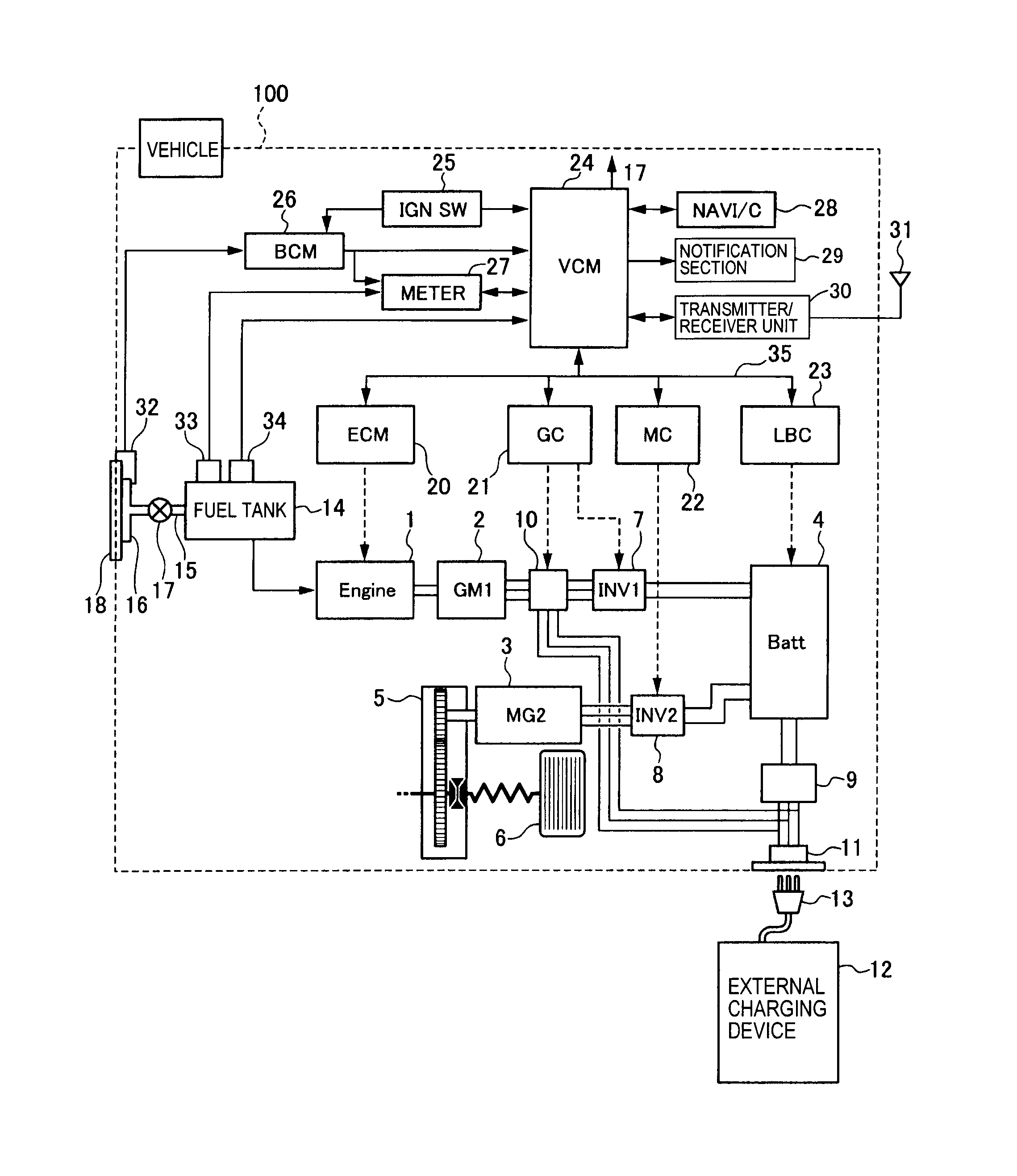
Non-positional. • Instructions and wiring diagram included in each relay .. Designed to control air conditioning, refrigeration ..
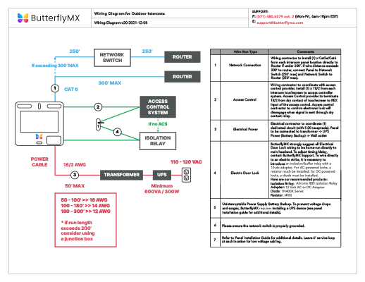
closed open closed. Mechanical Defrost Control These accurate multi circuit-timing devices can individually operate from 1 to 24 switches. Defrost Timer is rated to last 16 years longer double pole operaƟon and accurate temperature control.
&eatures and refrigeration applications while requiring intuitive installation set-up and dependable S DTAV40M. S ..
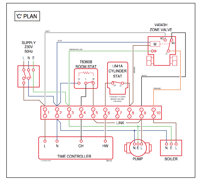
Wiring Diagram.A longer, more accurate defrost timer performance is greatly enhanced in a clean environment. Our raintight enclosure is well sealed to keep dirt and dust out of the timer gear train and all moving parts.
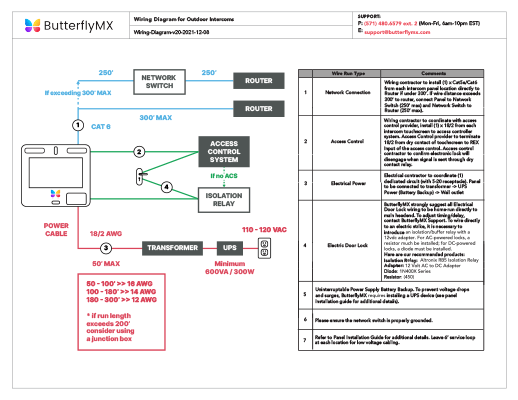
• Defrost control will determine when to stop the cooling to allow the frost and ice build-up to thaw • Decision is based either on a time schedule (defrost timer) or a precise reading of the temperature or pressure of your equipment (defrost control) ©. DEFROST CONTROL Decide the amount of defrost time necessary for your environment and the hours which you want defrost to occur.
Next, set the switches for each 15 min interval of defrost you require by moving the switch to the outer position. Each switch represents a 15 min interval of defrost and there are 4 intervals per hour.
of defrost desired Rotate small knob clockwise until time of day onlarge dial is opposite time painter To Wire Wire according to wiring diagram and conform to wring cades PRECISION MULTIPLE CONTROLS, INC 33 GREENWOOD • MIDLAND PARK, NJ FAX: precisionmulticontrols, corn CANADA MISSISSAUGA, ONTARIO. 1.

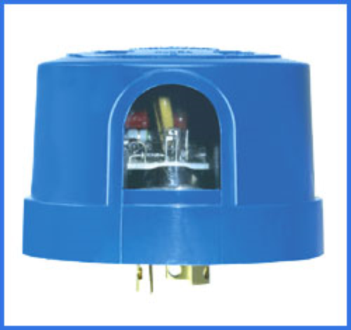
Photocontrol Wiring Diagrams. Always verify the incoming hot, load and neutral wires. Color codes cannot always be counted on as uniform or accurate, particularly on an old installation.
If you’re replacing an older photocontrol, make sure to note which were the hot, load and neutral wires. The color codes on the photocontrols are correct.controls – Independent Supply CompanyRefrigeration Basics – Controls
