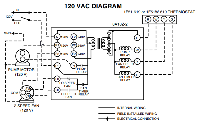
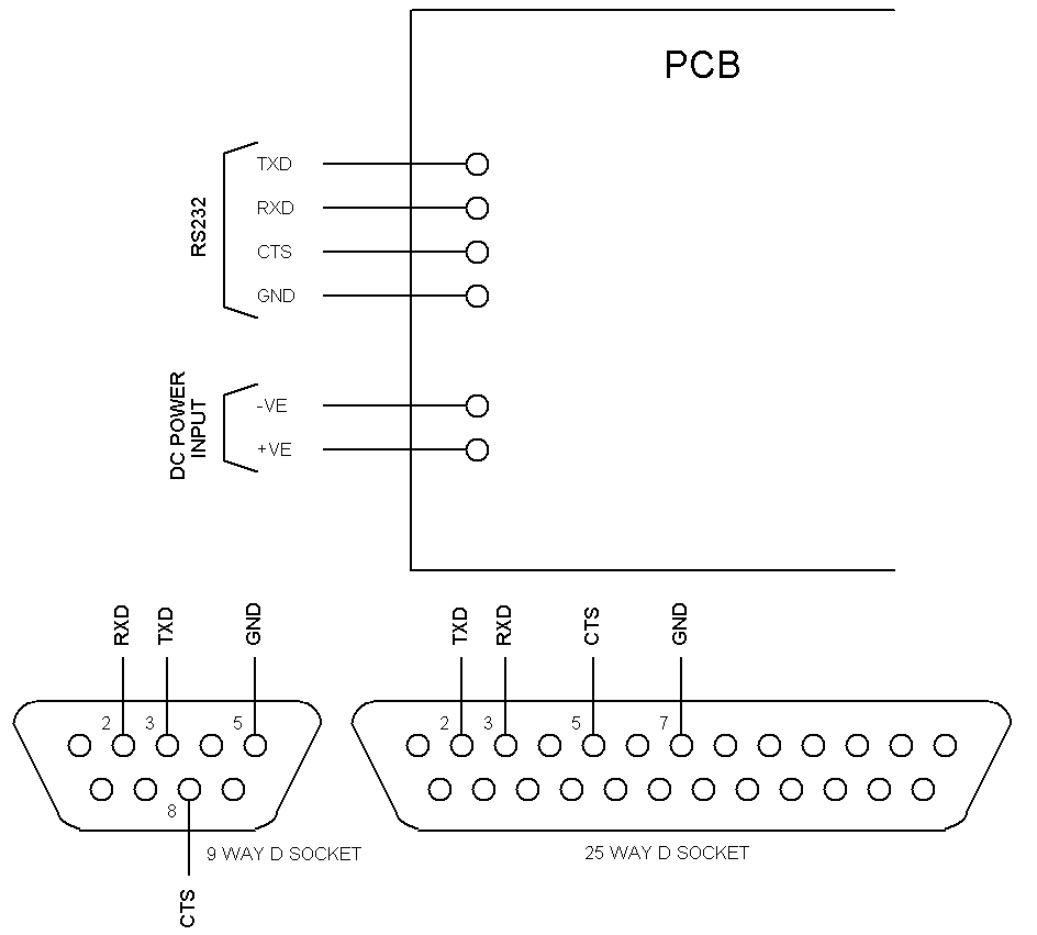
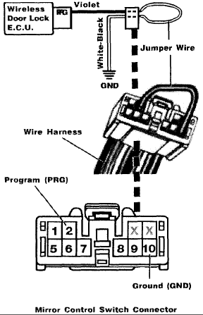
The iNES format implies 8 KiB of PRG RAM at $$7FFF, which may or may not be battery backed, . See also: Battery circuit schematic. i just purchased a RB-Prg 12 volt dc 12” stroke lb Force You can find a wiring diagramhere and wiring explanation in this video.
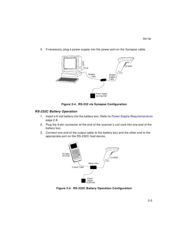
Wiring / looms Complete wiring kit for PRG Sport/E-tech model trailers ( XPRG) Main harness only for Beavertail /Tracsporter /Prosporter with super . Installation and Operation Instructions The GRX-RS and GRX-PRG allow up to eight GRAFIK Eye . Connect wiring as shown in the Wiring Diagram.
PRG SERIES ® ETHERNET SWITCH USER MANUAL. 1 + PRG Series ® Power and Data Distribution System Service Manual ().GRX-RS/GRX-PRG WIRING TERMINALS PC or A/V Equipment Mounting 1. Mount the GRX-RS/GRX-PRG on a 4″ x 4″ junction box or directly on a wall as shown in the Mounting Diagram.
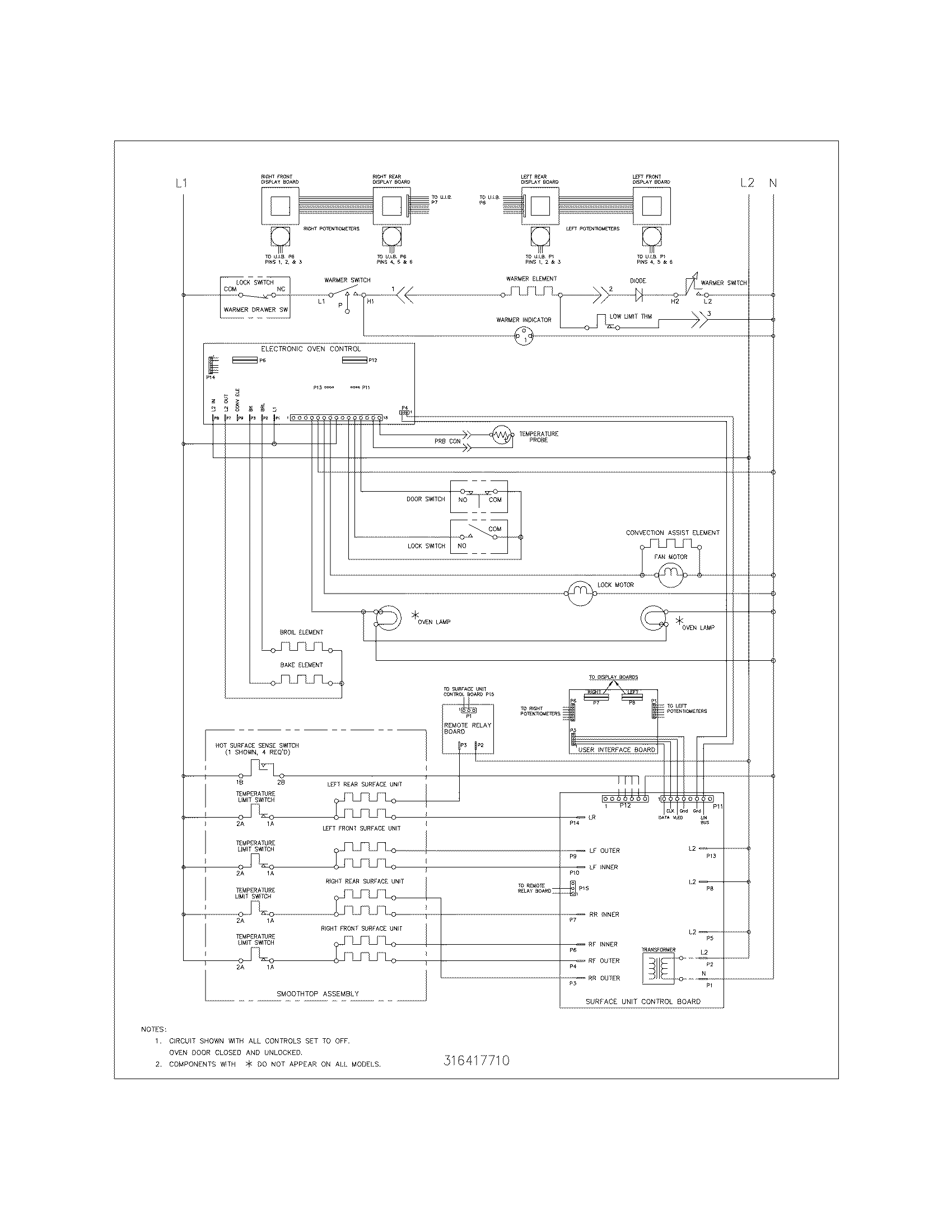
If metal conduit is not being used, ensure proper earth/grounding of the metal casing by connecting an earth/ground wire to the earth/ ground screw. Below is an image of a trailer wiring diamgram that is very helpful to reference.
Be sure to check out our trailer tips on how to wire a trailer and troubleshooting trailer lights. Trailer Wiring Diagram.
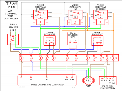
Wiring diagram software with built-in stencils for fast and efficient electrical wiring diagram design. Easy to create wiring plans, schematics, circuit diagrams and more. Normally wiring diagram refers to electrical schematic or circuits diagram.
wiring diagrams. Section 8W shows each connector and the circuits involved with that connector.
The connectors are identified using the name/number on the diagram pages. 8W – 01 – 8 8W WIRING DIAGRAM INFORMATION DR.
1 celica electrical wiring diagram (cont. next page) 1 2a a alt 1 2e 1 ia 25a dcc 7. 5a dome 7. 5a mpx–b 2 1 20a door 25a am1 5ioio 8 11 inin 14 in16 7 2f 13 ikin 6in3 1 acc am1 ig1 3 2 5 ik 8 ik tail off high low head flash hf h t el hu light control sw dimmer sw 16 c15 combination sw 13 7 12 ik 12 ii if ie a 9b 10 b 12 a 18 a 5a 19 a.Back-up Camera Interface – GM-K PRG (7″ screen) – NAV-TVWiring Diagram Software – Draw Wiring Diagrams with Built-in Symbols
