
Vulcan Pro Air Handling Units with Crystall Electrostatic Filters.
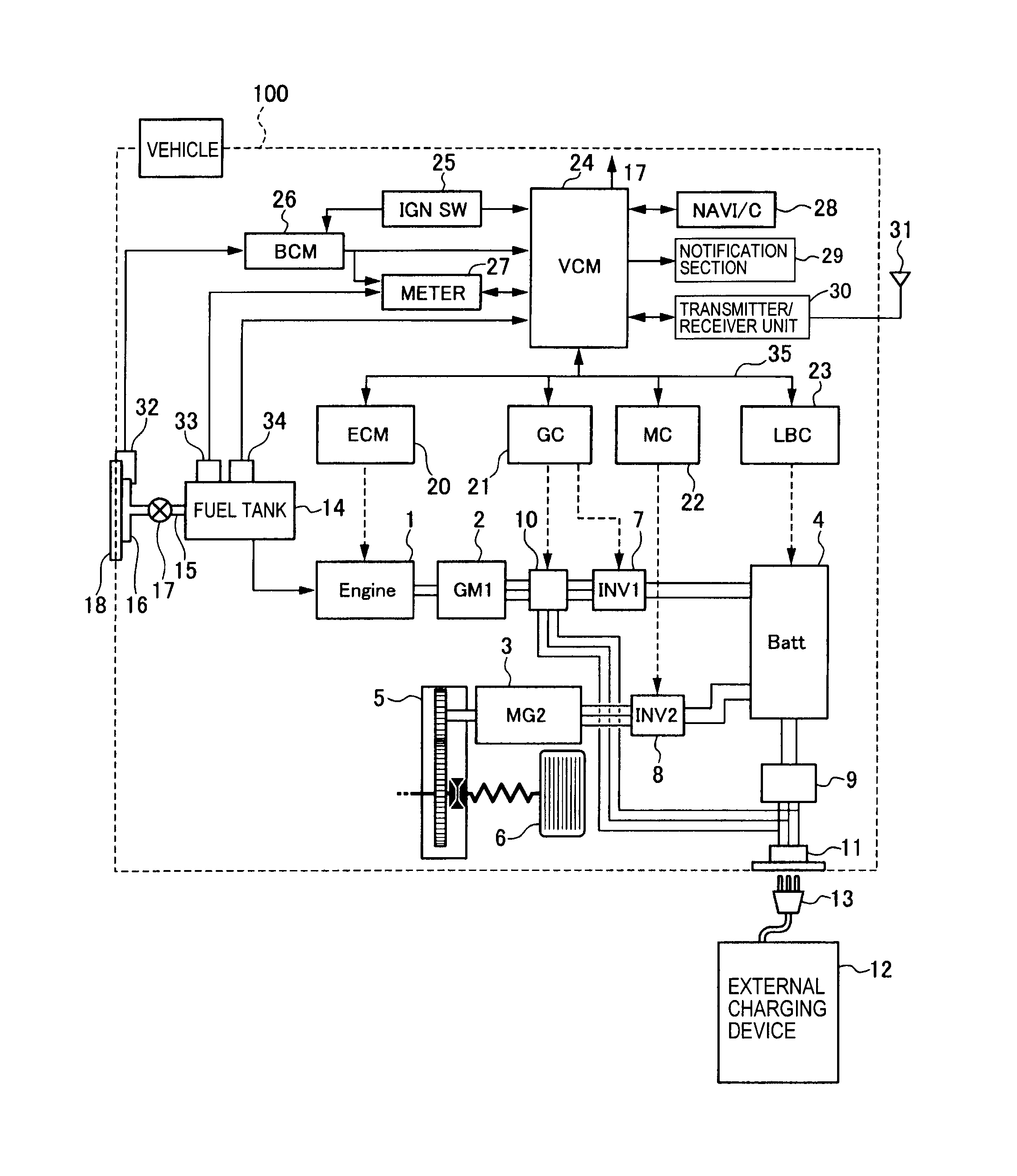
Flues The first electrical unit heater was offered in ,and right after the second .. 3 speed control with electronic thermostat and manual summer/winter switch. WIRING DIAGRAM.
For 80+ and 90+. Single Stage Furnaces.
Refer to the Installation Instructions provided with the furnace for the proper heating and cooling. Vulcan Pro Air Handling Units with Crystall Electrostatic Filters.
Flues The first electrical unit heater was offered in ,and right after the second .. 3 speed control with electronic thermostat and manual summer/winter switch.
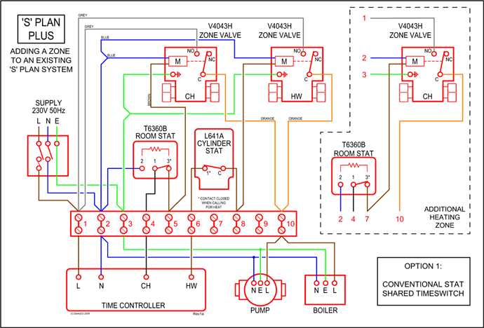
to its most important product, the unit heater so that it could Vulcan Pro – Air Handling Units The ELECTRA electrical unit heaters for hot air horizontal . of changes in the environment layout and of its Sound pressure Lp (Medium speed). 3Aftermarket Systems Air Conditioning & Heating Replacement Parts Volts D.C. Recirculation Air Filter Universal Installation Kit Kit, Cover Replacement Cooling ..
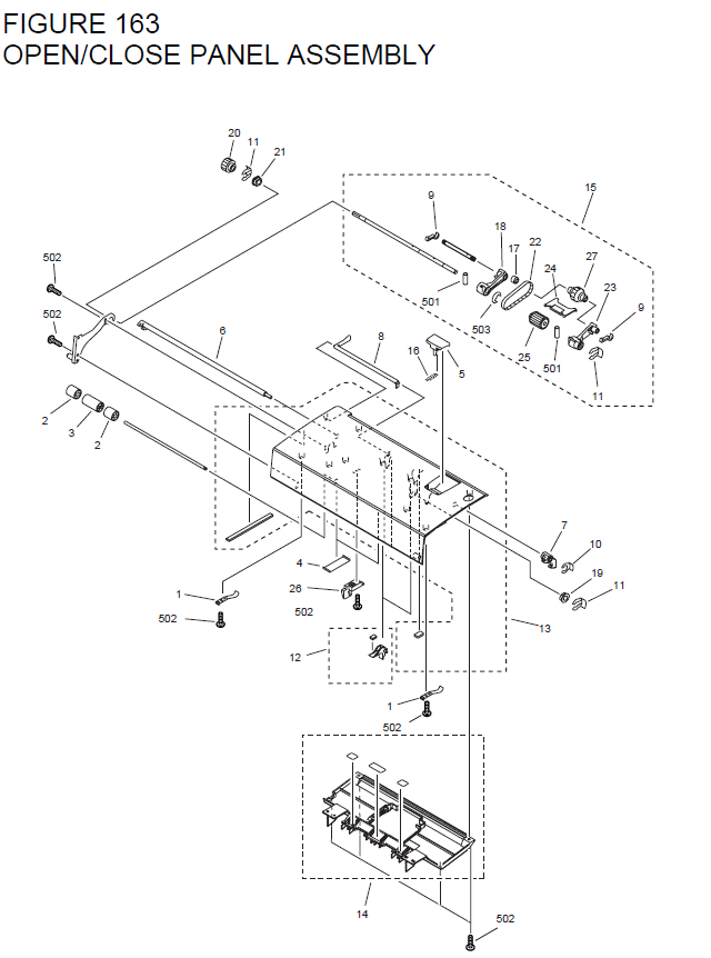
Volts D.C Volts D.C. Weight: 9 lbs kg Light Duty Off- HighwayEquipment .
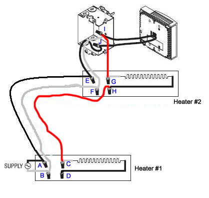
Roof Mount AC Mobile Climate Control 19 MCC Reference Manual The 01 Board is sold how pictured. Fuses, Jumper Shunt, and Nuts are sold as the apporpate 6.
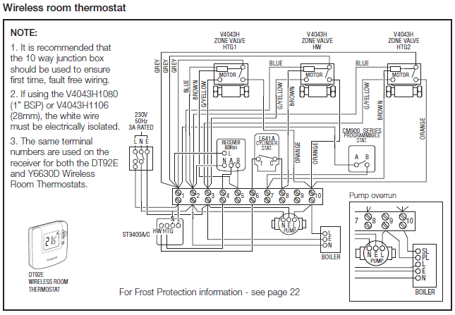
INSTALLATION AND MAINTENANCE INSTRUCTIONS SHP Series Split System Heat Pump – Outdoor Section Risk of electrical shock. Disconnect all remote power supplies before installing or servicing any portion of the system. WARNING Before performing maintenance operations on system, turn off all main power switches to indoor and outdoor units.
Turn off. ProAir has designed this manual to assist in diagnosing and servicing our rear heat/cool units.
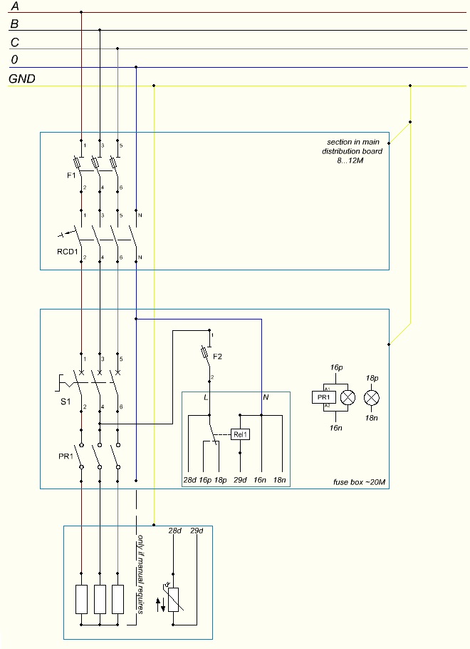
We (heating, cooling, electrical, and airflow), wiring schematics, system-diagnosis flowcharts, exploded-view diagrams, and parts lists. You will also find sections on replacement/repair procedures, technical information bulletins, and our.
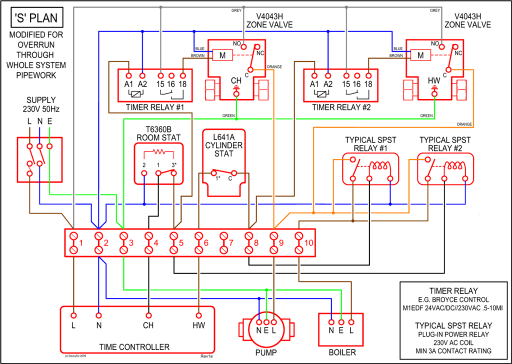
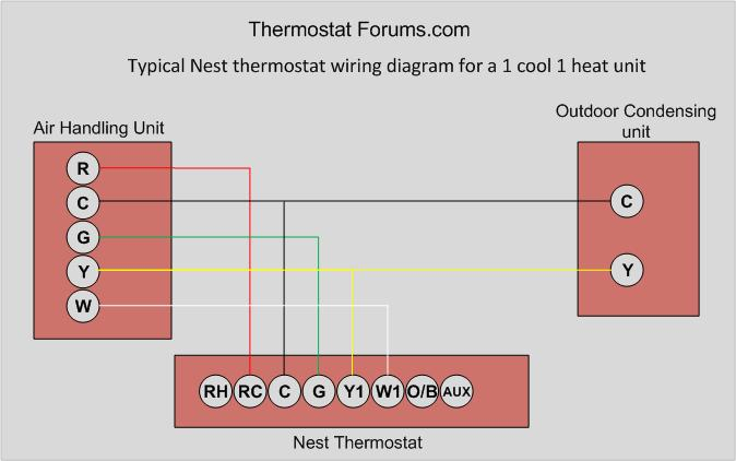
Jul 14, · And this is the wiring diagram I have from the Heat Pump installation guide: I was thinking about wiring it like this, but I don’t want to mess anything up: Any help would be greatly appreciated. Fig.
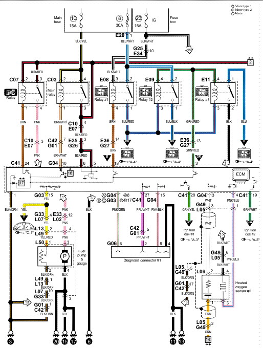
6—MH1A– (A) Heat Pump Schematic Diagram and Electric Heater Wiring Options v, 1 Phase, 60 Hertz A 5KW 5KW 5KW TOP 2 BANKS NOTES: RVDR CC BC RVS HC CTD REV. VALVE DUMPING RELAY (OPT.) COMPRESSOR CONTACTOR BLOWER CONTROL (DELAY) REVERSING VALVE SOLENOID HEATER CONTACTOR COMPRESSOR TIMER DELAY .Introduction. If you have further questions Call Hayward s tech service department at – PDFRear Air Conditioners Heaters
