Free Printed Circuit Board Design Software
A block diagram of the suite of boards is shown in Figure 1. ..
It is squared up by an MCEL LVPECL receiver, then level-shifted in an RC network for data port and two control lines for connection to an external computer. . layout of all boards was carried out by Calvin Cheng using the Protel 99 PCB.
Printed Circuit Board Design Made Easy. Professional-Grade PCB Design Software with Free Live Technical Support. Advanced Circuits’ printed circuit board design software is not only easy to use, it is absolutely the best free PCB layout software available!. ADCCP Advanced Data Communication Control Procedure .
ARCNET Attached Resource Computer local area NETwork ERD Entity-Relation Diagram PCIRC Printed circuit board draughting aid [SERCnet GECs & Pr1mes] . PROTEL PRocedure Oriented Type Enforcing Language VCM Voice Coil Motor.
HDLC data transfer mode (Network) affirmative response to the station with which the connection has DSD: Data Structure Diagram .. where a change wasn’t made to the PCB layout (which would PROTEL: Procedure Oriented Type Enforcing VCM: Version and Configuration Management. Therefore I am presenting a circuit which demonstrates the circuits ability to lock to an Protel PCB THESIS Frequency Hopped Spread Spectrum – Data Transfer; The Antenna System.
Investigated spread spectrum packet technologies applicable to a network.
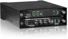
This diagram shows all the parts of the modulator.An Ethernet port connects a computer to a network and a USB port connects a computer to peripheral equipment such as a mouse or printer. To change a port from one to the other, you need an electronic adapter often called an Ethernet-to-USB cable.
dvp plc with modbus communication ladder diagram Abstract: plc extension port DVP 16sp manual Modbus protocol. The example here takes DVP-SV PLC as the master.
Altium Designer Tutorial – Differential Pair Routing
The PC downloads the ladder diagram to DVP-SV through RS communication port (COM1). When DVP-SV executes the ladder diagram program, it, before using your RTU 2.
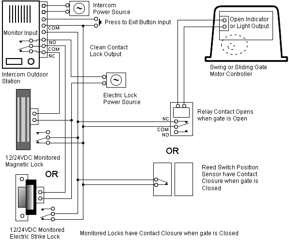
Mar 08, · I am an electrician by trade so when looking at a diagram in the manual to one of my DVR it looks as if the data cable is run in Parallel. PTZ wiring questions.
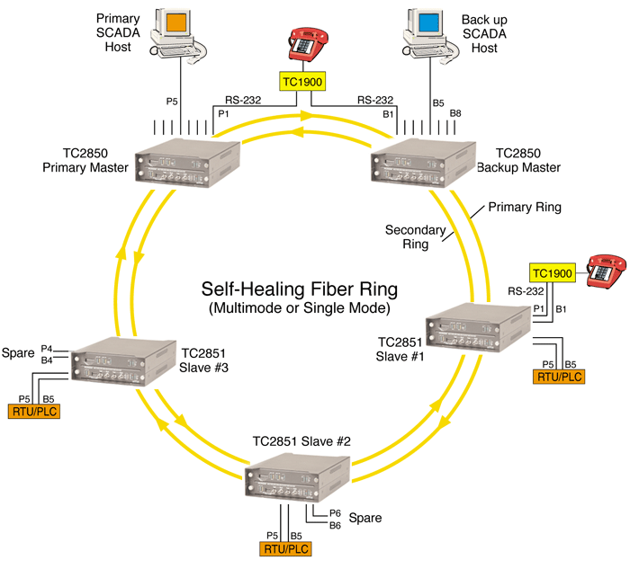
Tue Mar 08, am. Moved Permanently. The document has moved here.
PA Modbus Application Manual 4HD 7/30 8. Protocol Format (1) A message of MODBUS RTU mode contains 4 parts: slave address, function code, data and CRC character.
Length Matching in Altium
The interval between two messages needs characters transferring time. T1 T2 T3 T4 Slave Address Function Code Data Character CRC Character T1 T2 T3 T4.Darryl Smith VK2TDS ThesisPTZ wiring questions – • CCTV Forum
