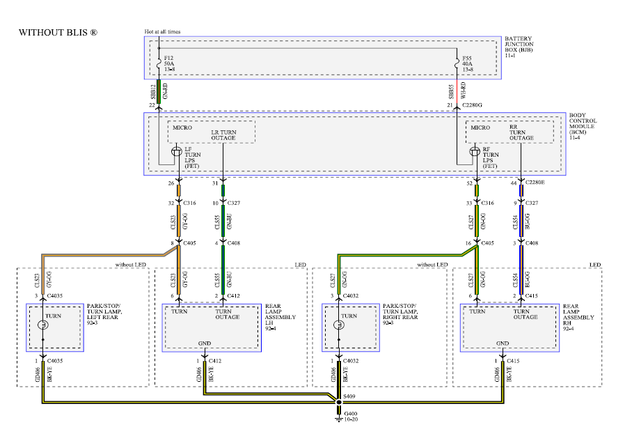
LR registering wrong Card Number/ Invalid Card · What badging system wiring diagram reader/doorphone How do I wire my eclipse readers to a PC?. Lenel OnGuard® Alternative Reader Wiring Guide.
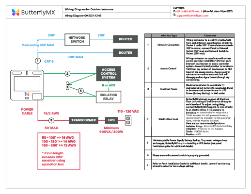
This guide is item This allows the software to function with these readers and cards. The reader.
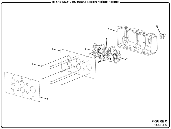
VARIO PROX CARD READER INSTALLATION MANUAL VERSION . Below is a diagram of how to program the reader using a programming card/tag.
Web page, E-mail – schematron.org MiniProx Reader Installation Manual sensitive receiver circuit that detects ID card data and passes it along to the Connect the Reader and Host together according to the wiring diagram with. VARIO PROX CARD READER INSTALLATION MANUAL VERSION .
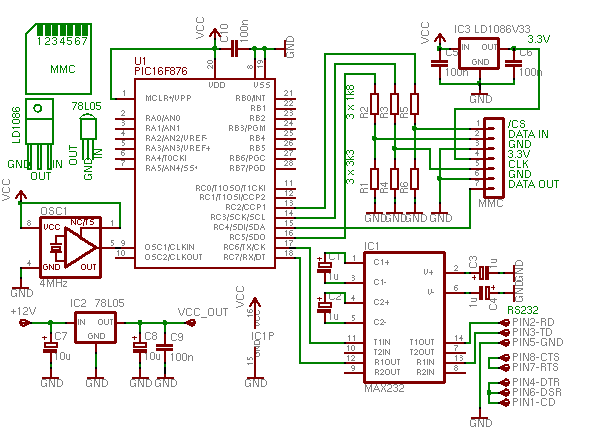
Below is a diagram of how to program the reader using a programming card/tag.reader and the steel surface to improve the read range. 7) The cables extending from the back of the PowerNet’s Pigtail cable comes in a standard 4 ft length.
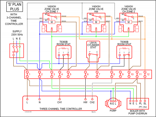
10 ft and 25 ft lengths Pigtails are optionally available. Plan for terminating the door wiring within that distance of the reader-controller. Access Control by Example Table of Contents | en 3 Bosch Security Systems Introductory Guide | | Table of Contents 1 Introduction 4 The example 4 2 Materials Planning 6 Planning the doors 6 Low tier: Electrical components 6 Card reader technologies 7 Credentials technology 7 Wiring for non-reader.
switch positioned on the end marked “CARD READER”. NOTE: Do not mix the dispenser control and credit card control data wires. Power Requirements CONNECTION INSTRUCTIONS FOR THE SYSTEM POWER SUPPLY, DISPENSER, MOTOR, AND ELECTRICAL GROUND CIRCUITS.
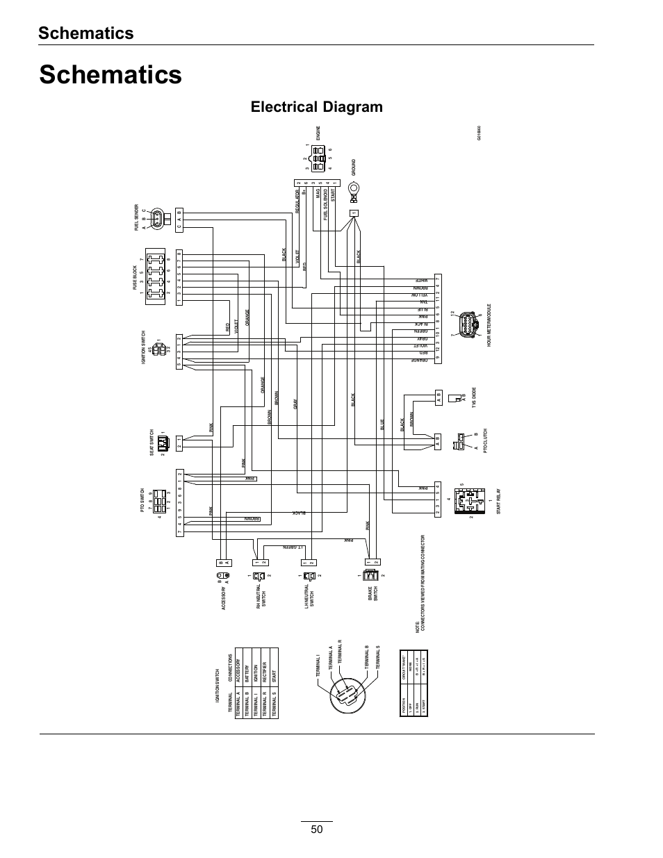
A.C. POWER REQUIREMENTS Figure1 Wiring Diagram for a PETROSMART EZ for Gilbarco System.
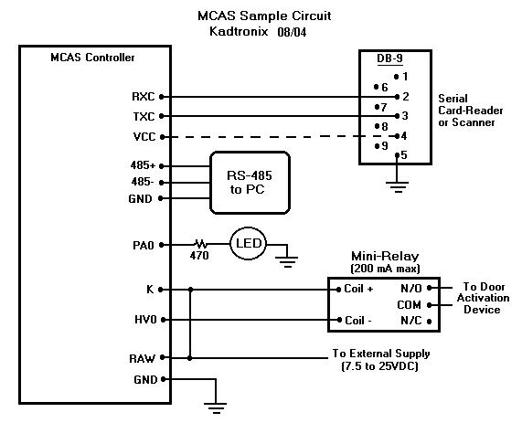
Card Reader Wiring Addendum For typical installations with power supply voltages of 12V and above, the connecting cable between the access control panel and card reader requires no larger than 22AWG conductors for up to feet. For power supplies below 12V, 18AWG conductors may be necessary to ensure proper data transmission. Always refer to.
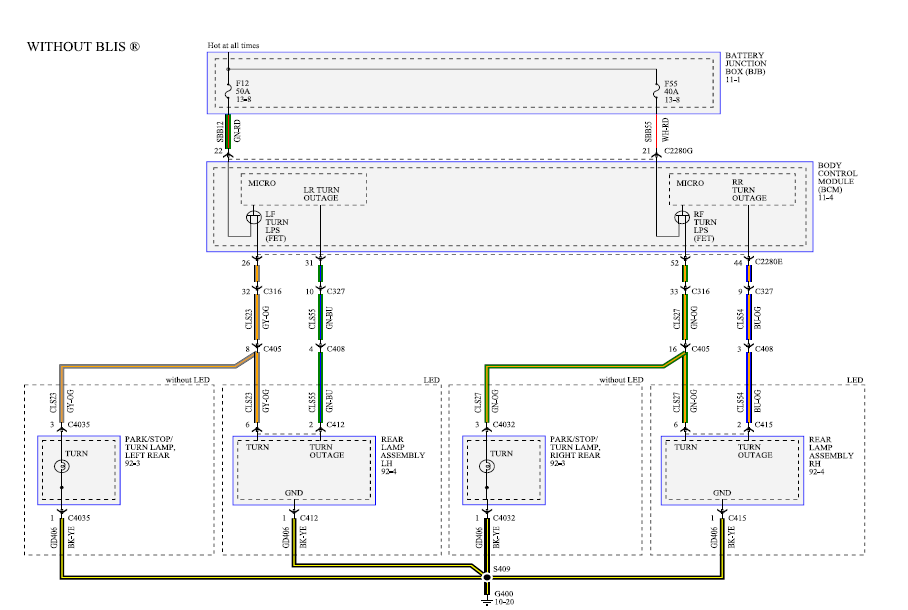
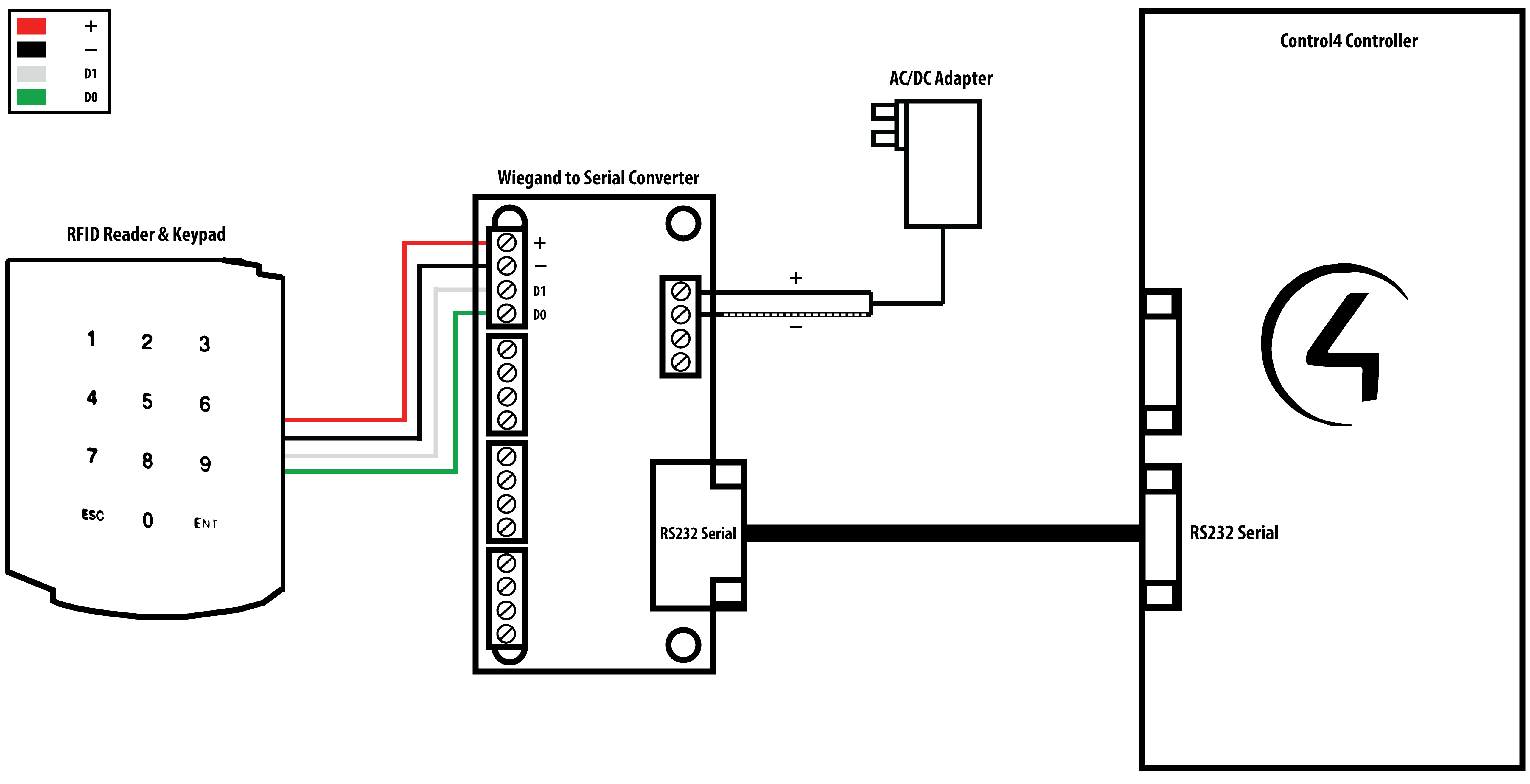
3. Connect the Reader and Host together according to the wiring diagram (below) and the Host installation guide. The legend for wiring is color coded (according to the “Wiegand Standard”) for the recommended cable, but marking the wires will make future maintenance easier.
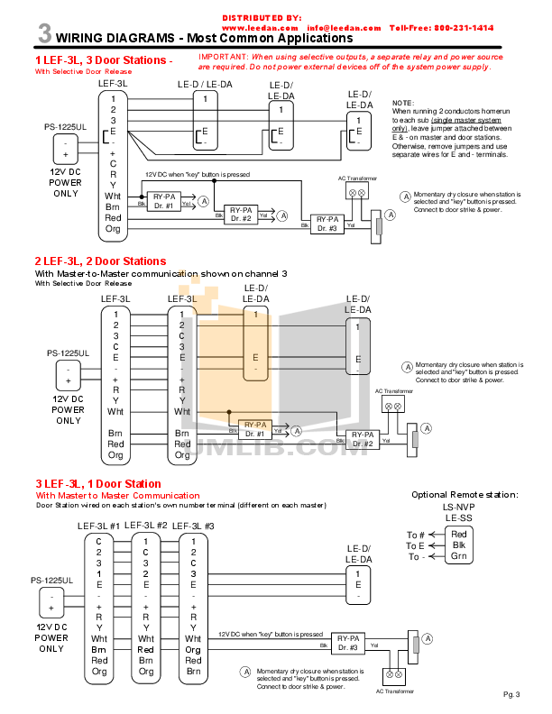
The color of the legend on the back label is the color of the respective.Basic SD Card Reader CircuitCommon wiring diagrams