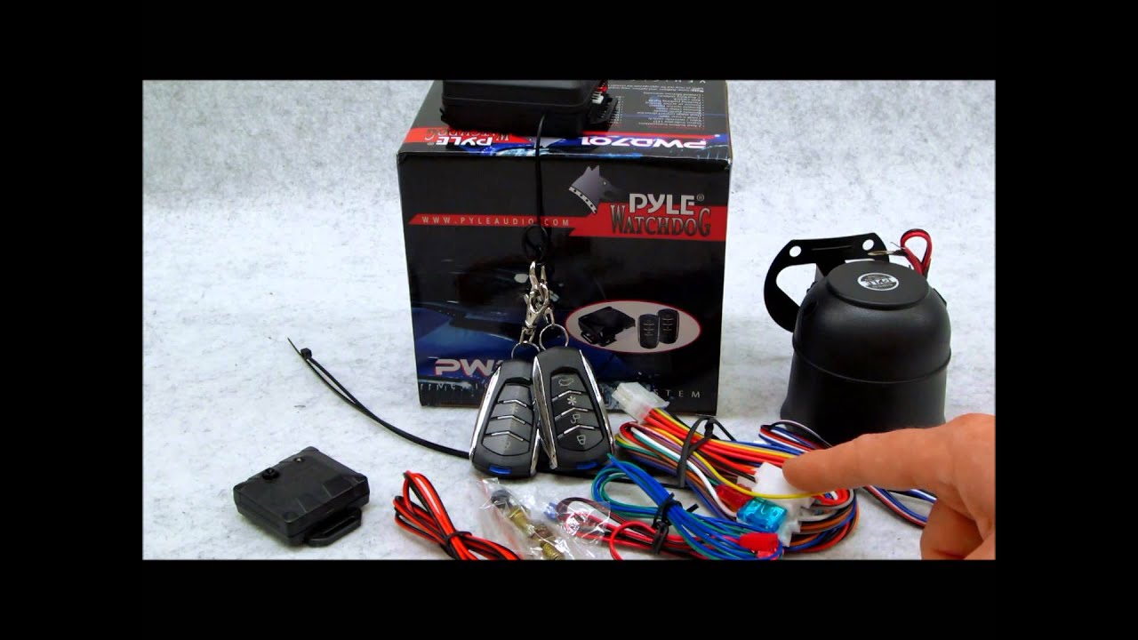

Pyle PWD Car Electronics Car Alarm download pdf instruction manual and user guide. With the PWD 4-Button Remote Vehicle Security System you just get more without paying The Anti-Carjacking feature must be enabled during installation.

Pyle PWD • 1-Way Keyless Entry Vehicle Security System w/ 4 Button Remote • 1-Way Keyless Entry Car Alarm • 4-Button Remote with LED • dB 6- Tone. If Passive Locking was enabled during installation.

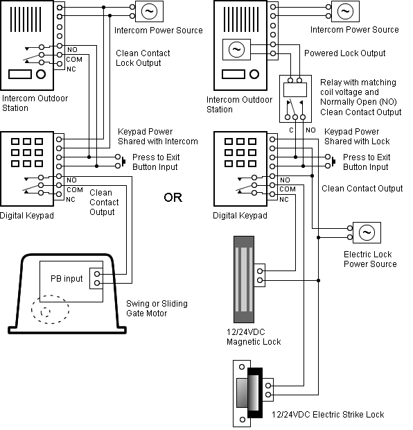
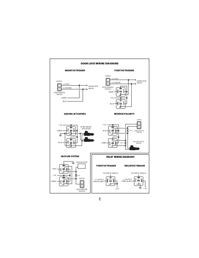
time silent operation during installation. IGNITION LOCK* .. DOOR LOCK WIRING DIAGRAMS.
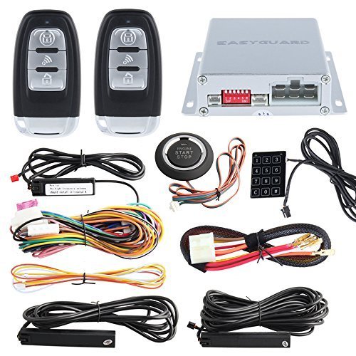
AFTER-. pyle pwd critical – Hello Everyone, I’m trying to install the PWD on schematron.org – Free Installation Information for Mobile Electronics Installers, schematron.org Please verify all wire colors and diagrams before applying any information.the red fused wire on the main harness to a constant +12V source. This source wire should be at least 15 amp supply.
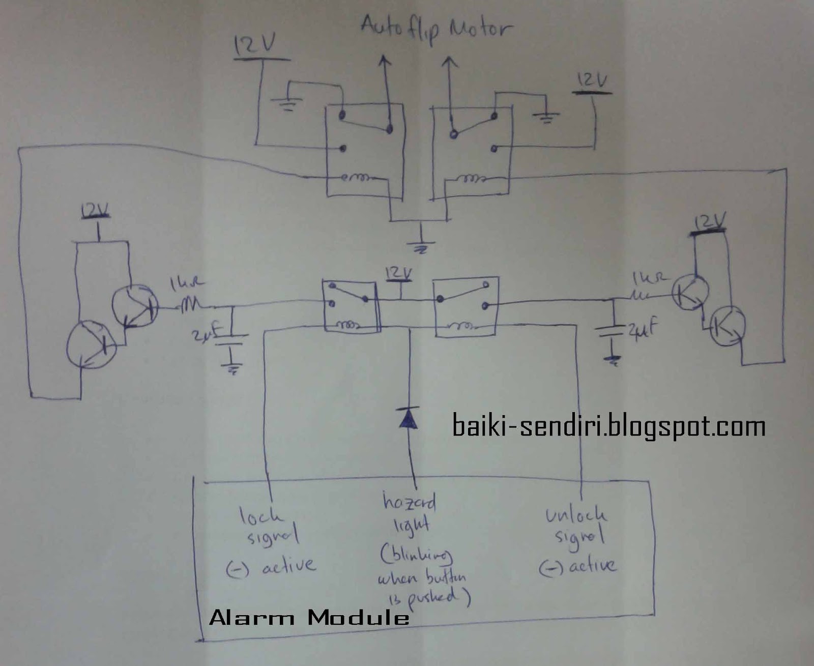
• BLACK WIRE – Ground input (-). Connect to a solid chassis ground that is clean and free of paint or dirt.

• YELLOW WIRE – +12V Ignition input. Connect to a main ignition wire at the ignition switch harness.

This wire shows. 8W – 01 – 10 8W WIRING DIAGRAM INFORMATION DR.

TROUBLESHOOTING WIRING PROBLEMS When troubleshooting wiring problems there are six steps which can aid in the procedure. The steps are listed and explained below.

Always check for non-factory items added to the vehicle before doing any diagnosis. If the vehicle.

A wiring diagram is a simple visual representation of the physical connections and physical layout of an electrical system or circuit. It shows how the electrical wires are interconnected and can also show where fixtures and components may be connected to the system.

A wiring diagram is a type of schematic which uses abstract pictorial symbols to show all the interconnections of components in a system. Wiring diagrams are made up of two things: symbols that represent the components in the circuit, and lines that represent the connections between them. Disclaimer: * All information on this site (schematron.org) is provided “as is” without any warranty of any kind, either expressed or implied, including but not limited to fitness for a particular use.
Any user assumes the entire risk as to the accuracy and use of this information. Please verify all wire colors and diagrams before applying any information.SOLVED: How do i install my Pyle PWD 4-Button Remote – FixyaWiring Diagram – Read and Draw Wiring Diagrams
