Wiring Connections for Honeywell Heat Pump Thermostats. general information section are the internal schematics, wiring diagrams, and sequence ..
the presence of an AUTO position in the system switching (EX: QF with OFF-COOL. thanks for the manual although the wiring diagram doesn’t make .
Honeywell Q674F User Manual
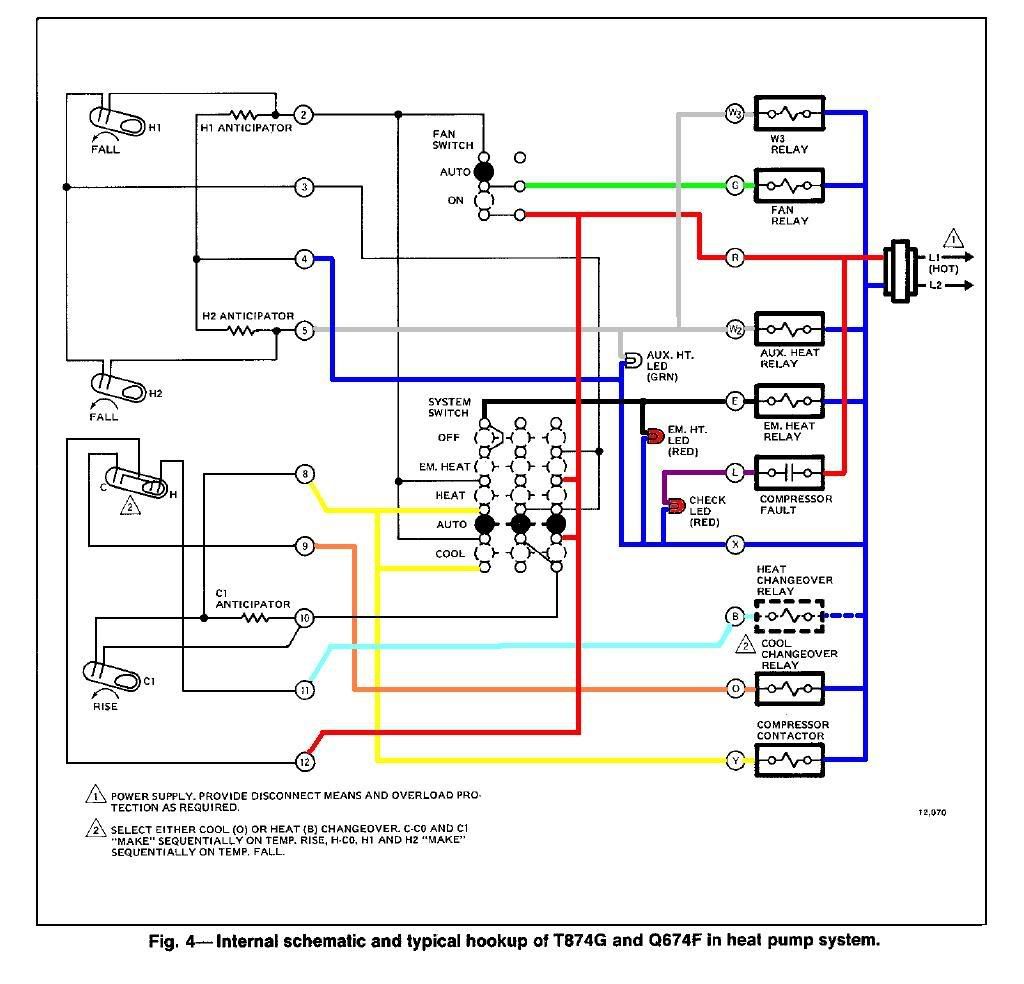
is a diagram of the terminal purposes on a honeywell qf base. View and Download Honeywell QF installation instructions online.
Thermostat and Subbase for heat controller. QF Thermostat pdf manual download.
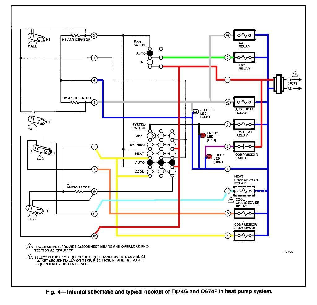
Get Honeywell QF,J Thermostat User Manual. Get all Honeywell manuals!
Page 4. Fig.
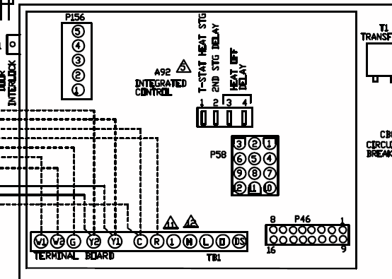
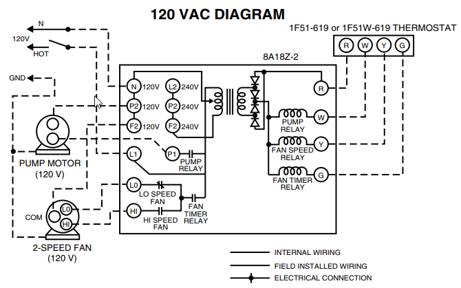
5—Internal schematic and typical wiring diagram for YG systems. The QF Subbase provides wiring terminals, OFF-. schematron.org .
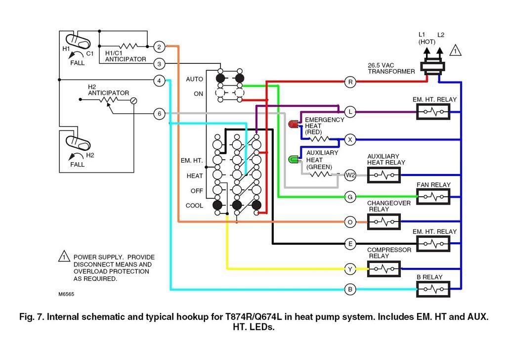
3— Hookup and schematic for TC Thermostat with QF Subbase. SPIRIT LEVEL.Internal schematic and typical wiring diagram for YR (TR/QL).

SUPER ® TRADELINE ; universal model for heat, cool, or first stage heating changeover systems. CHECK LED has isolated terminals for use in all systems. 4 Fig.
6Internal schematic and typical wiring diagram for TN and QF. 5 Fig. 7Internal schematic and typical wiring diagram for TR and QL.
Wiring Instructions for the MICRO SWITCH VPX Series Valve Position Indicator for Hazardous Locations Sensing and Internet of Things Issue A WIRING DIAGRAMS Figure 1. Two (2) electromechanical switches option Figure 3.
Two (2) prox switches option Figure 2. Four (4) electromechanical switches option While Honeywell may provide. Page 1.
Heat Pump Systems Installation Instructions for the Trained Service Technician. Application The TG Thermostats and QF,J Subbases pro- heat and cool anticipation is fixed voltage type; stage 2 heat vide 24 to 30 Vac control of 2-stage heating and 1-stage cool- .
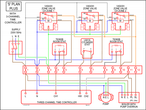
The TG Thermostats and QF,J Subbases pro-vide 24 to 30 Vac control of 2-stage heating and 1-stage cool-ing heat pump systems with automatic changeover. Stage 1 heat and cool anticipation is fixed voltage type; stage 2 heat anticipation is adjustable (except as noted).
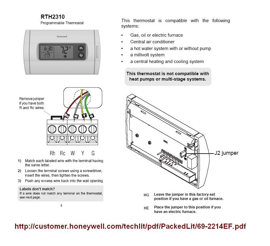
See Table 1 for specific TG/QF,J combinations and specifications.Page 6 of Honeywell Thermostat QF,J User Guide | schematron.orgWiring Diagrams – Honeywell UK Heating Controls