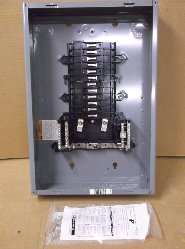
This bulletin contains instructions for the installation and operation of QO™ and Homeline™ load centers. It also includes installation instructions for standard. Main lugs and main circuit breaker load centers have wire binding screw tightening values on the wiring diagrams and circuit breaker labels.
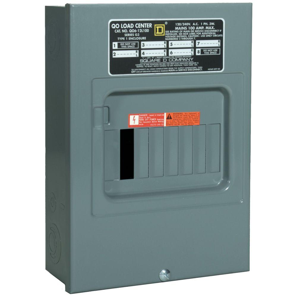
Neutral Assemblies. Main lugs and main circuit breaker load centers have wire binding screw tightening values on the wiring diagrams and circuit breaker labels.
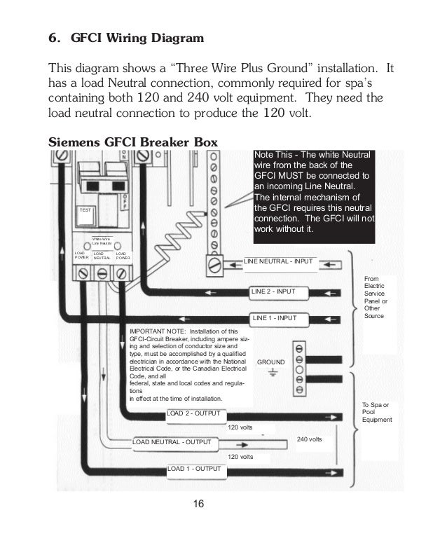
Neutral Assemblies. QO Load Centers are built on the Square D This ensures proper alignment without manual marked on the load center label and/or wiring diagram. QO Load.
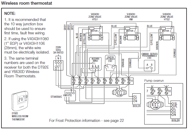
QO® Circuit Breaker Load Centers from Square D® are Underwriters. Laboratories (UL) .
torque values on the wiring diagrams and circuit breaker labels.Square D QO Generator Interlock clip. This model fits and amp QO panels with a vertical main breaker. Kit Includes: Instructions, Labeling, Drill bit, Interlock Clip, and holding schematron.org: $ Avoid the inconveniences that an unexpected power outage can cause with this QO Indoor Generator Interlock Kit.
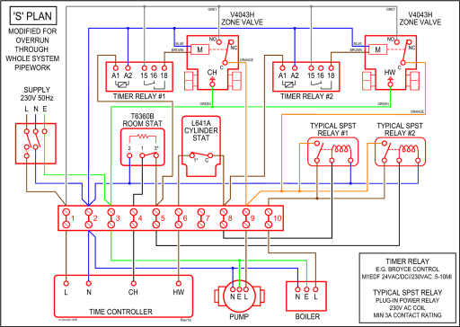
The Square D QO Cover Generator and QOM2 Frame Size Main Breaker Interlock Kit is used to direct generator power to any circuit within your home. Readbag users suggest that PDF is worth reading.
The file contains page(s) and is free to view, download or print. Look at the flashlight batteries, pretend they’re rechargeable NMHs, that means they are volts each..
In this case the batteries represent the stator windings, and if we go across the batteries in series we’d measure from terminal (1) to terminal (7). Fukuoka | Japan Fukuoka | Japan.QO™ and Homeline™ Load Centers | Schneider ElectricSquare D Interlock Kit | eBay
