Page 1. Page 2.
Page 3. Page 4.

Page 5. Page 6. Page 7.
Page 8. Page 9. Page Page Page Page Page Page Page Page Page Connect the equipment into an outlet on a circuit different from that to which the . support posts into the control retainer holes as shown in the diagram below.
A compatible Listed 4-wire detector is the Radionics, Inc. D in a D or.
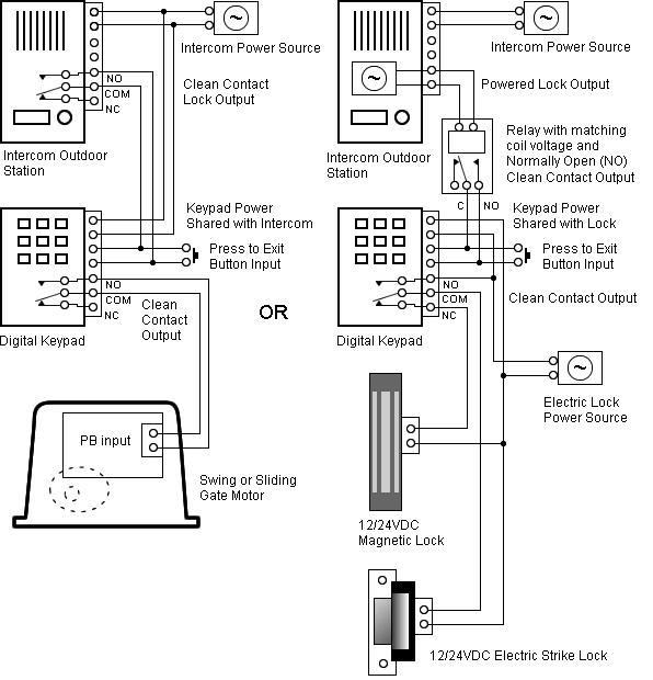
D/D Operation and Installation Guide. Page 2. © Bosch Security System Wiring Diagrams, Issue A..
D/DTH w/. D Base.
Affects: D and DTH Smoke Detectors. Our Quality Assurance at () Wiring Methods for Radionics Smoke Detector Bases. available in two and four wire models with an optional °F (57°C) fixed- temperature Notice: Radionics, Inc.
makes no claim written, oral, or implied that the D specified in the Base Compatibility chart in the Technogram Introduction • This document supplements the Security System User’s schematron.org presents a number of advanced commands for system administrators and others who perform security system management functions. Refer to the Security System User’s Guide for the basics of system operation, including basic system com- mands and definitions of terms. Using interconnect wiring Interconnect wiring connectors parallel the SDI2 terminals (27 through 30 (or 23 through 26 if configured for SDI2)).
In installations with multiple SDI2 modules, using interconnect wiring makes the installation quicker and easier than using terminal strip wiring. You use any. Radionics D Installation Manual.
Control/communicator. Radionics D, 12 V Ah battery for fire and combined fire/burglary systems.
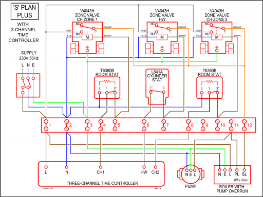
When using the D’s Point 1 as a fire point, the number of devices you can connect to it’s sensor Power restricted for fire and combined fire/ loop is limited. Page System Wiring Diagram, Issue A.
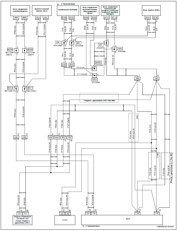
Presented here for your delectation is a super simple three dial radionics schematic. There is no techno jargon, or standard schematic imagery.
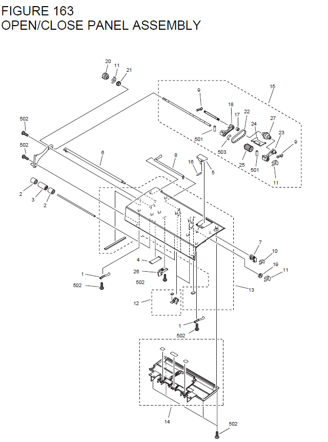
The circuit is simple as shown. The black lines represent wires, and their connections.
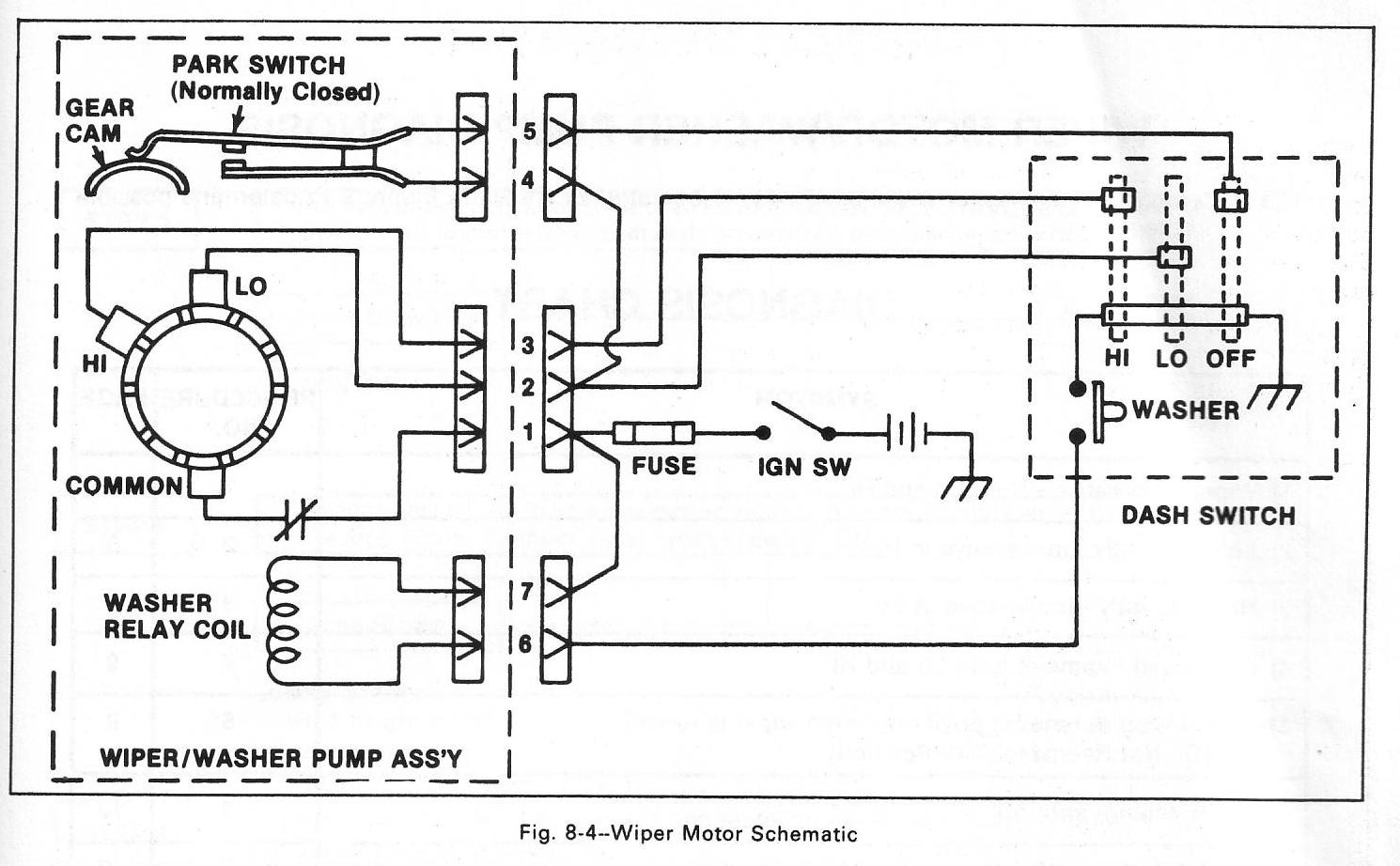
The bottom row of wiring simply shows that the last post on each potentiometer is connected to the last post on. DG Operation and Installation Guide (this document) DG Program Entry Guide DG Program Record Sheet DG Release Notes DMUX Operation and Installation Guide DG/DG/DG Installation and Troubleshooting Quick Reference Guide RAM IV Operations Manual D Installation Manual | schematron.orgRADIONICS D INSTALLATION MANUAL Pdf Download.
