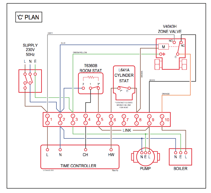
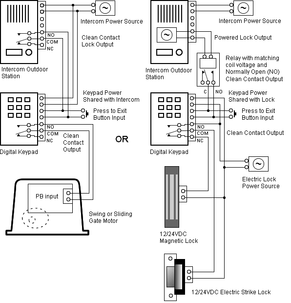
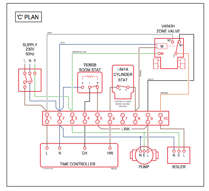
starter wiring for various Rain Bird controllers. Figure 1: This is a basic pump start wiring diagram for most controllers. This diagram assumes the Master Valve.
Connecting to the valvesE Connecting to the valvesEach valve connects to the timer through two wires. One wire from each valvesolenoid must.
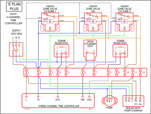
We have 1 Rain Bird PCPS manual available for free PDF download: Owners Manual / Operating Manual / Installation Manual. Rain Bird PCPS Owners Manual / Operating Manual / Installation Manual (14 pages) Dual Program Sprinkler Timer. RAIN BIRD Maxi-Paw Impact Sprinkler Manual; RAIN BIRD IMPACT SPRINKLER .
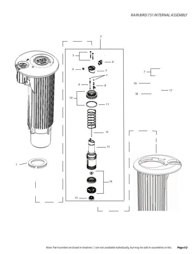
FIGURE 2 STEP 2: CONNECTING THE WIRING How to choose the .. mainline for booking up the air hose (see item C in the diagram on .
PCPS , TSC-7, EZ-1, and RC-7Bi (or any Rain Bird RC-Bi or RC-I series). 4.
Parts & Accessories
Sprinkler Timer. Owners Manual / Operating Guide / Installation Guide .
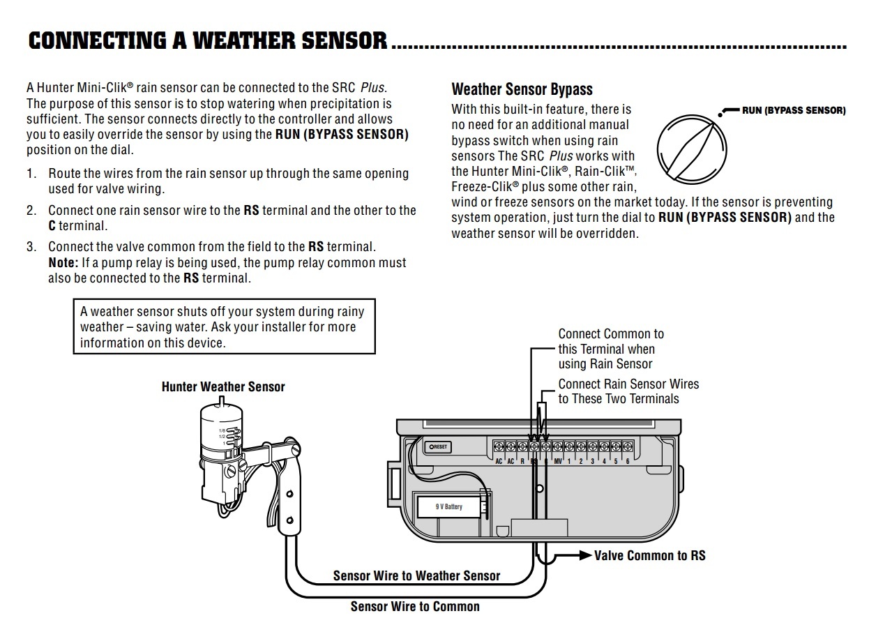
PC and PC and 3/4 amp for PCPS and PCPS) and should not be.Rain Bird Product Manuals for all of your Rain Bird Products. + + The Do-It-Yourself Sprinkler Store. Learn.
Support. Contractors.
Login. Local Classes Webinars Videos Wire & Electrical Burial Wire, Wire Connectors, Cable Ties, Wiring Tools, etc. Water Conservation Green Controllers & Timers, Green Weather Sensors, etc.
Glue & Primers PCV. Page Wiring Connections.
Wiring Connections Connect Master Valve Connect the valve wires for each station and for a Connect an optional Master Valve to the ESP-Me (optional) Master Valve, Pump Start Relay or Rain controller. Sensor. 1. Route the master valve wires through a knock-out Connect Valves opening at the bottom or back of the unit.
Let Rain Bird help you with a FREE referral to top local contractors near you who can help select and install the best sprinkler system for your yard. Just enter your zip code and get a list of pre-screened professionals in your area.
This wiring diagram shows us the wiring for four controllers wired to one pump starter, and one Common wire for all valves on all four controllers. If more than one controller is in operation at the same time, Controller A takes precedence over Controllers B, C and D; Controller B will take precedence over C and D; Controller C will take prece-. ESP-MC Wiring Diagram GREEN WHITE TO VALVES RED BLACK ESP-MC Wiring Diagram GREEN WHITE TO VALVES RED BLACK ESP-MC Wiring Diagram GREEN WHITE TO VALVES RED BLACK ESP-MC Wiring Diagram GREEN WHITE TO VALVES RED BLACK ESP-MC Wiring Diagram Card (up) Created Date: 12/15/ PM.Rain Bird PCPS ManualsRain Bird PCPS Manuals
