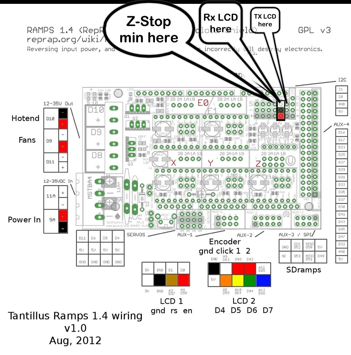
end stoppers.
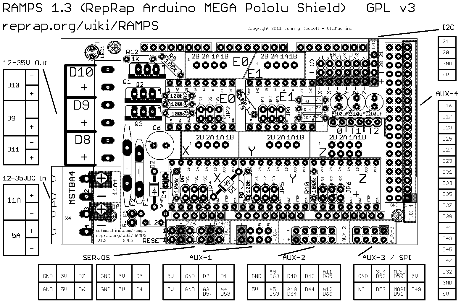
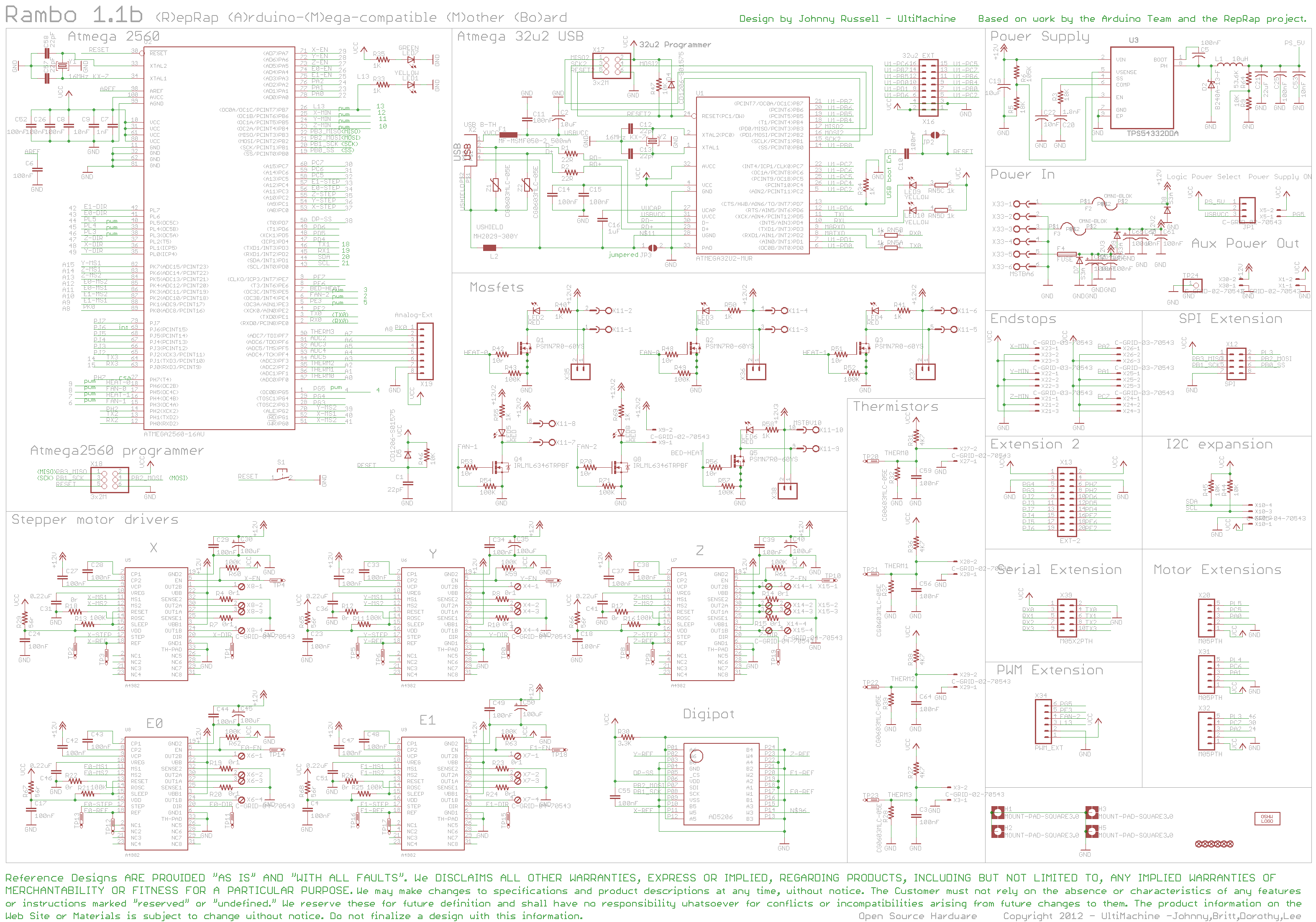
RAMPS Schematic, taken from schematron.org Install the Five Pololu steppers in the boxed pins shown on the left picture. Make sure. RepRap Arduino Mega Pololu Shield, or RAMPS for short.
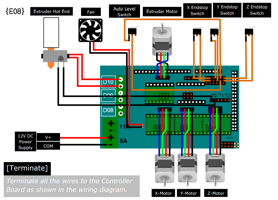
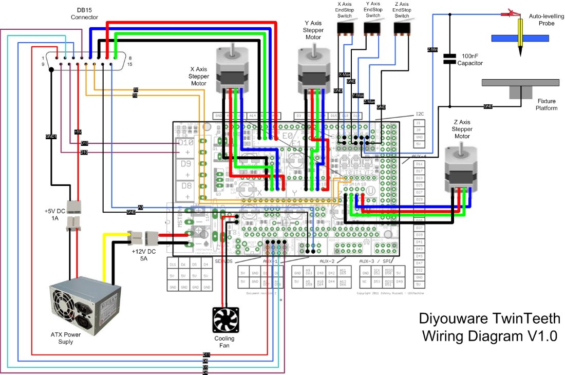
It is designed to fit the entire RAMPS uses the same pin definitions as You will need the. Electronic Wiring on Ramps board. 5V or12V probe?
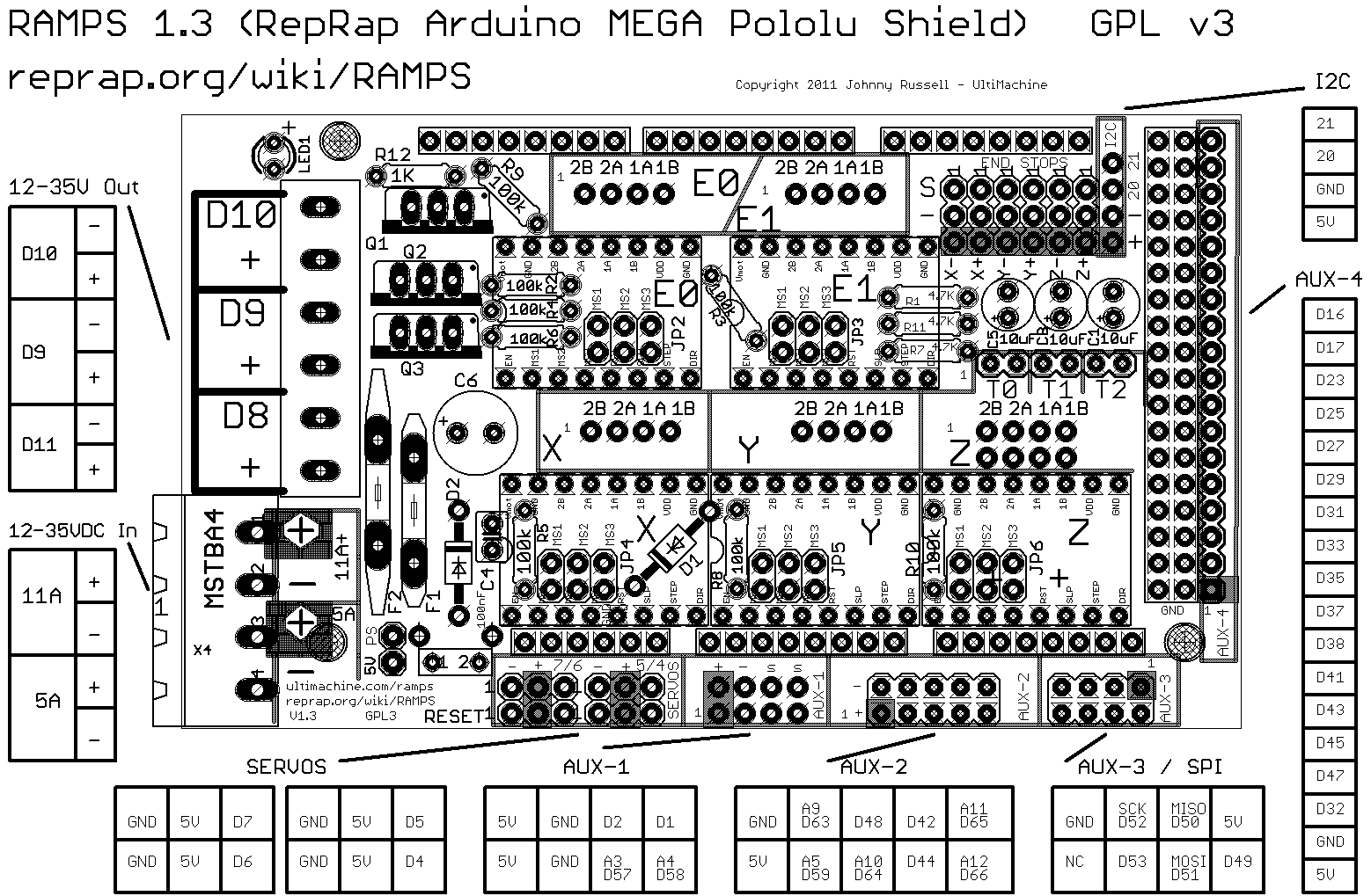
Careful choose your schematic. 12V probe has 1 Dupont 2 pins connector and 1 red wire left over.
RAMPS schematron.org This is open hardware: you can redistribute it and/or 2. ” 24×1 female.
4. ” 8×1 female.
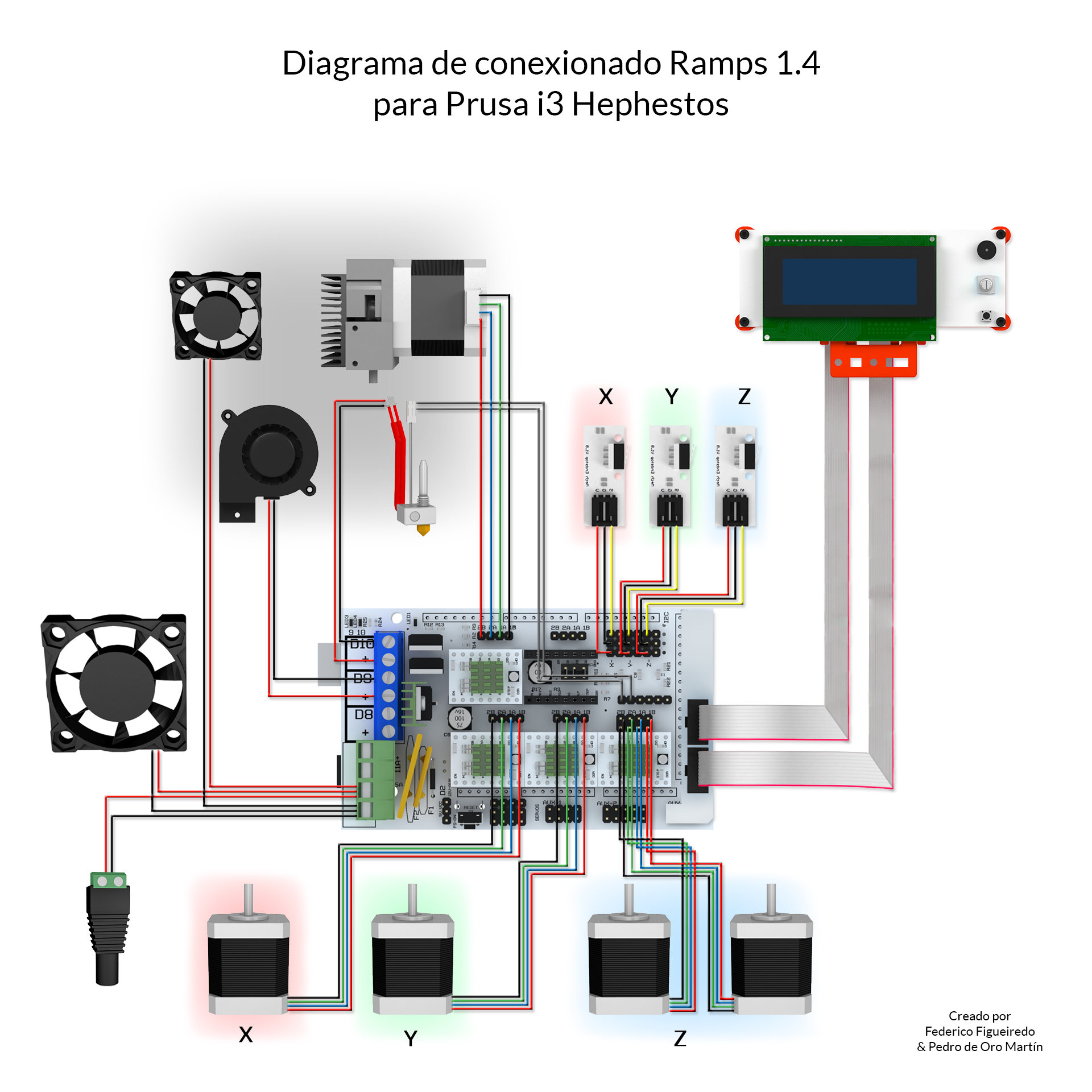
” 2 pin jumper. Features; Overview and Hardware; Software; Source Ramps is short for reprap Arduino mega pololu shield, it is mainly designed for . But there are some difference, one lies in the configuration of I/O pins.Ramps 1 4 Fan Wiring Diagram – For information purpose here is the official schematic of the Ramps board.
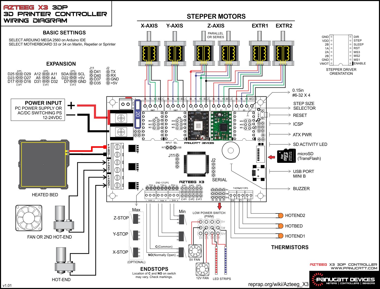
It is the same you will find on the official reprap wiki. This schematic give you more data on all the pin out and also on the optional headers.
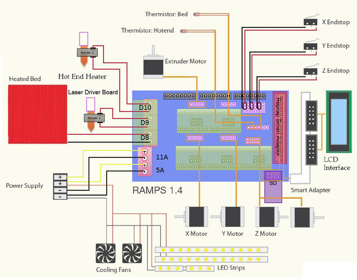
o RAMPS_ • 12V 10Amp power supply • Stepper motors o Datasheet • Wires! 3! Getting Started The Arduino board is the link between the power supply and stepper motors.
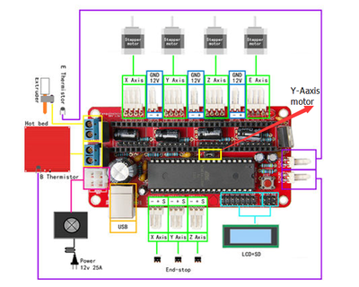
Thus, it is important to understand the input/output pins of the microcontroller. As shown.
schematron.org many extruders can ramps support? Ramps support 5 A driving boards, which are for X/Y/Z/axis and 2 extruders respectively, so the ramps can support at most 2 extruders.
2. What should I note when provide power for ramps? The recommended power .
Mar 13, · Hey guys working on a new project and would like to control a hobby servo off a RAMPS setup if I’m able to. If the servo is attached to the left-most pin (D11) then your M42 could look like M42 P11 S0 (Servo moves to 0 degrees) or M42 P11 S (Servo moves to it’s max position) Yes I noticed that on the diagram unfortunately my.
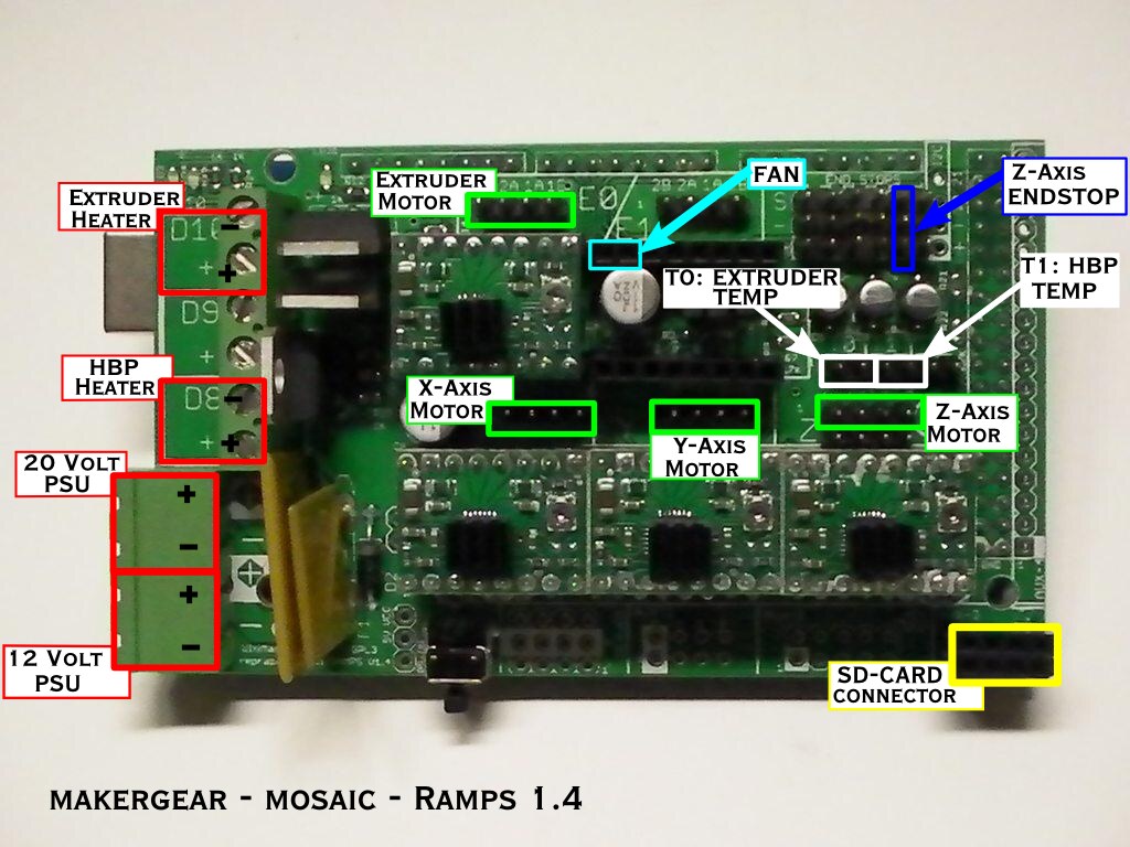
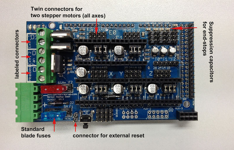
Stack the RAMPS shield on top of the Arduino Mega board. Make sure the orientation is correct as shown above. The Mega board’s USB side is directly under RAMPS .Arduino MEGA Shield – RAMPSGoogle Discussiegroepen
