Before starting any electrical repairs or adjustments, ensure the power is turned off and the battery is disconnected. The following instructions will help you navigate the essential wiring structure and components responsible for power transfer and control.
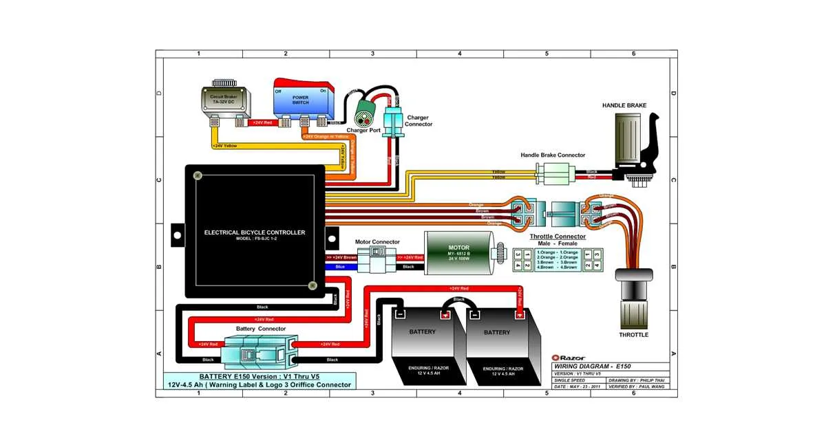
Begin by identifying the main connections between the motor, controller, and throttle assembly. The motor’s terminals should be securely connected to the controller’s output ports. Be mindful of polarity: reversing connections could lead to malfunction or potential damage to the system.
Next, focus on the brake and throttle wiring. The throttle usually integrates with a three-wire connector–red for power, black for ground, and a third for signal transmission. Check for any loose or frayed wires in this area, as it can disrupt responsiveness.
Pay attention to the battery pack’s wiring as well. The positive terminal of the battery should align with the controller’s input for proper voltage regulation. Faulty connections here can result in insufficient power to the motor, or worse, short-circuiting the entire system.
Ensure each wire is properly insulated and secured to prevent contact with any moving parts. It’s also crucial to verify the continuity of all circuits with a multimeter before reassembling the scooter. Double-check the alignment of connectors, and once satisfied with the setup, carefully reconnect the battery and test the scooter.
If unsure of any steps, consider seeking professional help to avoid irreversible damage. Electrical components in scooters can be sensitive to improper handling, so it’s important to proceed cautiously.
Electrical Connection Overview for Electric Bike

Start by identifying the battery terminals. Connect the positive terminal to the motor controller input, ensuring a secure and corrosion-free connection. The negative terminal should be linked to the frame or designated ground area to ensure proper current flow.
Next, the motor wiring should be routed through the controller, following the specified color codes to avoid errors in phase connections. Typically, the three wires from the motor will be connected to corresponding terminals on the controller. Double-check the continuity before securing any connections to avoid shorts.
The throttle mechanism needs to be wired directly into the controller’s throttle port. Ensure that the wiring is free of kinks or abrasions. If the throttle has a display, the appropriate data wire should be securely attached to the controller for accurate speed readings.
For brake switches, the wiring should be integrated into the controller’s brake terminals. These will typically be connected in series with the motor’s power lines to cut off current when brakes are engaged. Verify the brake cut-off function works before reassembling any components.
Finally, make sure all connections are insulated and that the motor controller is mounted in a well-ventilated area to prevent overheating. Ensure that all wiring is tightly secured, avoiding any slack that could become entangled with moving parts.
Understanding the Key Components of the Razor MX350 Electrical System

The heart of any electric scooter’s power system lies in its battery, motor, and control connections. These elements form the backbone of the machine’s ability to move efficiently and reliably. Understanding how each part interacts is crucial for both troubleshooting and performance optimization.
Battery: The power source is the first point of focus. Ensure the battery is correctly connected and providing adequate voltage. A 24V sealed lead-acid battery is typically used, and it’s important to check for any loose terminals or corrosion. Overcharging or deep discharging can lead to battery failure, so use a charger designed for the system’s specific requirements.
Motor: The motor is the driving force of the scooter. Check the connections between the motor and power control system. Look for any fraying wires or damage to the motor itself. If the motor is not responding, ensure there is no short circuit and that it is properly connected to the control unit. Overheating can also cause issues, so make sure it is not exposed to excessive load.
Throttle Control: The throttle is what regulates the power sent to the motor. A malfunctioning throttle can cause jerky acceleration or total lack of movement. Inspect the throttle’s cable and connections to ensure they are not worn out or pinched. It’s also important to check the electrical connection between the throttle and the control board to ensure smooth signal transmission.
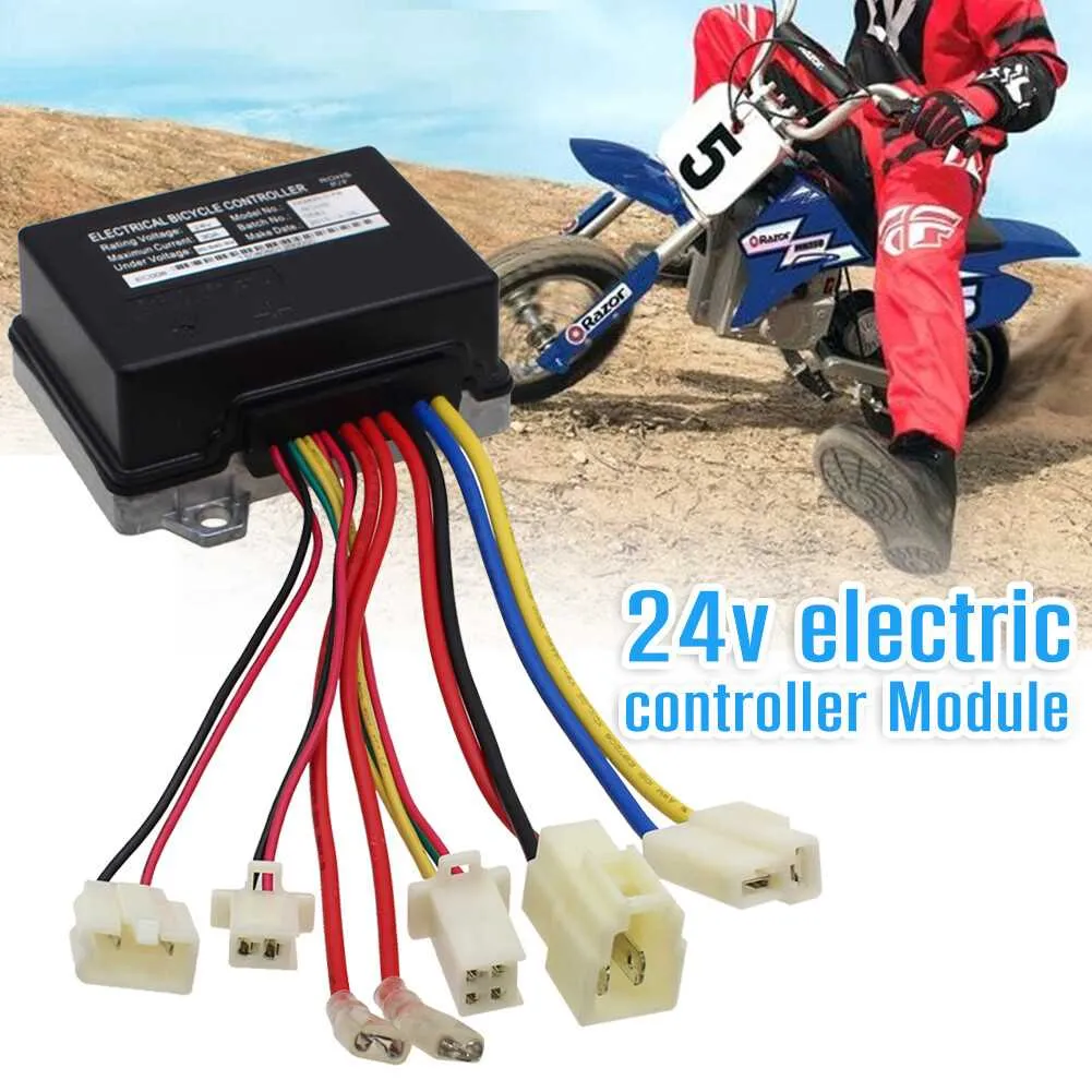
Controller: The controller acts as the brains of the system, regulating the flow of electricity based on inputs from the throttle and other sensors. A faulty controller can result in erratic power delivery or failure to start. Check for any damaged or burned components, and confirm all wiring is intact and firmly connected.
Brake System: The brake system, including both the hand brake and foot brake, plays a role in the electrical setup, especially in models with an integrated brake switch. Inspect the wiring leading from the brake handles to the control unit to ensure they are properly connected. Any short or disconnection can disable the scooter’s braking function.
Switches and Fuses: Safety features such as the on/off switch and fuse play a critical role in preventing overloads and short circuits. Test the switches for proper operation and replace any blown fuses with the correct rating to ensure reliable protection against electrical surges.
By thoroughly inspecting each of these components and maintaining proper connections, you can ensure the longevity and performance of the electric scooter.
Step-by-Step Guide to Connecting the Motor and Controller
First, ensure the power is off before starting the installation process. To connect the motor and the controller correctly, follow these steps:
1. Locate the motor wires and identify the three main leads: positive, negative, and ground. These are usually color-coded, with red for positive, black for negative, and green for ground. Be sure to match the corresponding wires from the controller.
2. Find the corresponding terminals on the controller. Typically, the controller will have labeled ports for each wire: motor positive (often marked as M+), motor negative (M-), and ground (GND). Double-check that each wire is connected to its correct terminal on the controller.
3. Use secure connectors or solder the wires in place to ensure a stable electrical connection. If using connectors, ensure they are tightly attached to avoid any loose connections during operation.
4. After connecting the motor leads to the controller, verify the other components, such as throttle and brake, are properly connected to the controller. These should be securely linked before turning the power on.
5. Recheck all connections for any signs of loose wires or shorts. Once satisfied, turn the power back on and test the motor to ensure it functions as expected.
Here is a summary of the connections for easy reference:
| Connection | Wire Color | Terminal Label |
|---|---|---|
| Motor Positive | Red | M+ |
| Motor Negative | Black | M- |
| Ground | Green | GND |
Troubleshooting Common Electrical Issues in Electric Dirt Bikes

If your electric dirt bike isn’t running correctly, electrical malfunctions are often the cause. Here are some steps to help you identify and resolve the problem:
- Check the Battery Connections: Loose or corroded terminals can prevent the motor from receiving power. Ensure the connections are clean and tight.
- Inspect the Controller: The controller regulates power to the motor. If it’s malfunctioning, you may experience erratic behavior or no power. Test the controller with a multimeter for any faults.
- Examine the Throttle Wiring: A broken or disconnected throttle wire can cause the bike to stop responding to throttle input. Check for frays or loose connections along the throttle cable.
- Inspect the Motor Connections: Loose or damaged wires at the motor can result in intermittent power loss. Carefully check all wires attached to the motor for signs of wear or disconnection.
- Look for Short Circuits: Shorts in the system can cause failure in multiple components. Look for exposed wires that might be touching metal parts or other wires.
By systematically inspecting these areas, you can often pinpoint and resolve common electrical issues that prevent your bike from functioning correctly.