
If you’re interested in radio communication and are looking for a detailed diagram and guidebook for the RCI 2980 radio, you’ve come to the right place. The RCI 2980 is a popular amateur radio transceiver that offers a wide range of features for both beginners and advanced users. With its excellent performance and durability, it has become a go-to choice for many radio enthusiasts.
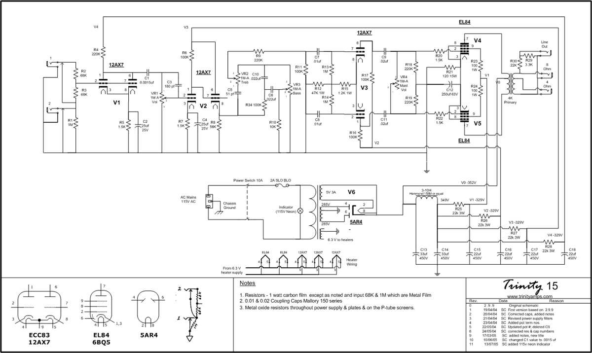
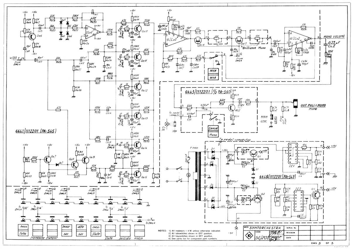
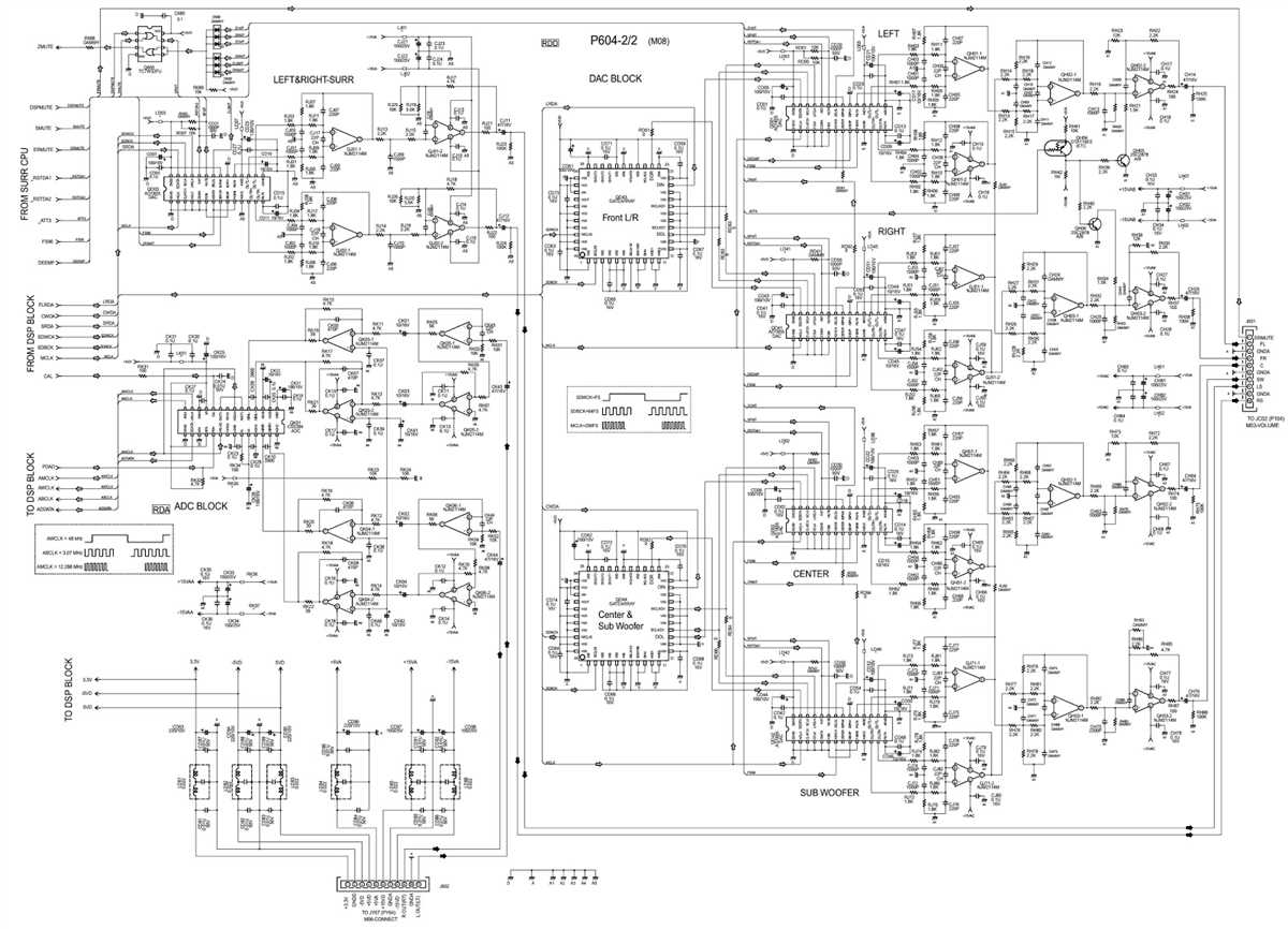
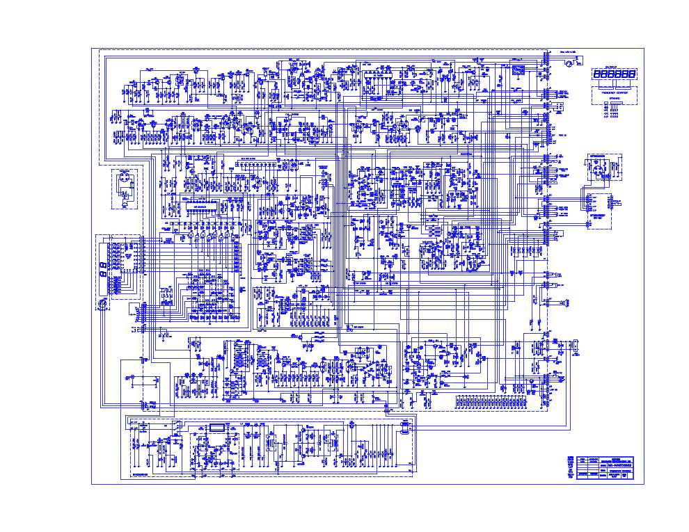
The RCI 2980 schematic is a blueprint that provides a visual representation of the various components and connections within the radio. It outlines the circuitry, wiring, and layout, making it easier for users to understand how the radio works and to troubleshoot any issues that may arise. Whether you’re a hobbyist or a professional, having access to the RCI 2980 schematic can greatly enhance your experience with this radio.
By studying the RCI 2980 schematic, users can get a better understanding of the radio’s internal workings and can make modifications or upgrades to customize their radio experience. The schematic also allows users to identify specific parts and their locations within the radio, making it easier to diagnose and repair any problems that may occur. With this information at hand, users can troubleshoot and resolve issues on their own instead of relying on professional assistance.
In conclusion, the RCI 2980 schematic is a valuable resource for anyone interested in the RCI 2980 radio. It provides a detailed visual representation of the radio’s circuitry and connections, allowing users to better understand its workings and troubleshoot any issues. Whether you’re a beginner or an advanced radio user, the RCI 2980 schematic is a must-have tool for enhancing your radio communication experience.
Rci 2980 Schematic: A Comprehensive Guide
The Rci 2980 is a popular base station CB radio known for its reliable performance and user-friendly design. If you are an owner or an enthusiast of this model, understanding its schematic diagram is essential for troubleshooting and making modifications. This comprehensive guide aims to provide you with a thorough understanding of the Rci 2980 schematic and its various components.
At the heart of the Rci 2980 is its main circuit board, which houses the key components of the radio. The schematic diagram of this board shows the connections between these components, including the power supply, audio circuits, transmission circuits, and receiver circuits. Understanding these connections is crucial for diagnosing and solving any issues that may arise.
Power Supply Section
The power supply section of the Rci 2980 schematic is responsible for converting the incoming AC voltage to DC voltage that powers the radio. This section typically includes a transformer, rectifier diodes, capacitors, and voltage regulators. By following the schematic, you can identify the different components and their connections, helping you troubleshoot any power-related issues.
Audio Circuits
The audio circuits in the Rci 2980 schematic handle the transmission and reception of sound. This section includes components such as microphones, amplifiers, and speakers. By understanding the connections between these components, you can easily make modifications or diagnose any audio-related problems.
Transmitter and Receiver Circuits
The transmitter and receiver circuits are the core of the Rci 2980, responsible for transmitting and receiving radio signals. These circuits consist of components such as transistors, capacitors, and inductors. By studying the schematic, you can identify these components and their connections, enabling you to troubleshoot any signal-related issues effectively.
Modifications and Customizations
One of the advantages of understanding the Rci 2980 schematic is the ability to make modifications or customizations to the radio. By following the schematic, you can identify the specific components or connections that you want to modify, allowing you to enhance the performance or add additional features to the radio.
In conclusion, the Rci 2980 schematic is an invaluable resource for owners and enthusiasts of this CB radio model. By studying and understanding the various components and connections depicted in the schematic, you can troubleshoot issues, make modifications, and customize the radio to your liking.
Understanding the Components of Rci 2980
The Rci 2980 is a popular CB radio model known for its advanced features and reliable performance. In order to fully understand how this radio operates, it is important to familiarize oneself with its various components and their functions.
Main Unit
The main unit of the Rci 2980 houses the core components of the radio, including the circuit board, power supply, and frequency control. This unit is responsible for powering the radio and controlling its various functions. It is usually housed in a sturdy chassis to protect the internal components.
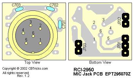
Microphone
The microphone is an essential component of the Rci 2980, as it allows the user to transmit their voice over the airwaves. The microphone typically features a push-to-talk (PTT) button that activates the transmission, as well as various control buttons for adjusting the volume, squelch, and other audio settings.
Display
The Rci 2980 is equipped with a built-in display that provides important information to the user. This display usually shows the current frequency, channel, signal strength, and other relevant data. Some models may also include additional features such as a clock or backlight for improved visibility in low-light conditions.
Antenna
The antenna is an integral part of any CB radio system, including the Rci 2980. It is responsible for transmitting and receiving signals, allowing the radio to communicate with other radios within range. The Rci 2980 is typically compatible with a variety of antenna types, including whip antennas and magnetic mount antennas.
Controls and Buttons
The Rci 2980 features a range of controls and buttons that allow the user to customize their radio experience. These may include knobs for adjusting the volume and squelch levels, buttons for selecting channels and frequencies, and switches for toggling various features such as the RF gain or noise blanker. These controls are designed to be easily accessible and user-friendly.
Understanding the various components of the Rci 2980 is essential for anyone using or considering purchasing this CB radio model. By familiarizing oneself with the main unit, microphone, display, antenna, and controls, users can make the most of the radio’s features and capabilities.
How to Read and Interpret the Rci 2980 Schematic

If you are interested in understanding how the Rci 2980 radio works and how to troubleshoot any issues, it is essential to be able to read and interpret its schematic diagram. A schematic diagram is a visual representation of the electrical circuitry of a device, showing the connections between components and their functions. Here are some guidelines on how to read and interpret the Rci 2980 schematic diagram effectively:
1. Identify the components:
The first step in reading the Rci 2980 schematic diagram is to identify the different components present in the circuit. The diagram will include symbols and labels for each component, such as resistors, capacitors, transistors, diodes, and ICs (integrated circuits). By understanding the symbols and their corresponding components, you can easily follow the circuit’s flow.
2. Trace the circuit path:
Once you have identified the components, you can start tracing the circuit path from the power source to the output. The schematic diagram will have lines connecting the components, indicating the flow of electricity. By following these lines, you can understand how the different components are connected and how current flows through the circuit.
3. Understand component functions:
Each component in the Rci 2980 schematic diagram has a specific function within the circuit. It is important to understand the purpose and operation of each component to troubleshoot and analyze the radio effectively. For example, resistors control the flow of current, capacitors store and release electrical energy, and transistors amplify or switch signals.
4. Note voltage and current values:
The schematic diagram will often include voltage and current values for different parts of the circuit. By noting these values, you can compare them to the expected values and identify any discrepancies that may indicate a faulty component. Understanding the voltage and current values will help you diagnose problems and make accurate repairs.
5. Pay attention to signal flow:
In a radio circuit like the Rci 2980, there will be various signal paths for transmitting and receiving signals. By following these signal paths in the schematic diagram, you can understand how the radio processes and amplifies the incoming signals. This knowledge will be beneficial when troubleshooting signal-related issues.
In conclusion, being able to read and interpret the Rci 2980 schematic diagram is crucial for understanding the radio’s operation and diagnosing any problems. By identifying the components, tracing the circuit path, understanding component functions, noting voltage and current values, and paying attention to signal flow, you can effectively analyze and troubleshoot the radio’s electronic circuitry.
Troubleshooting Common Issues with RCI 2980
The RCI 2980 is a popular radio model used by amateur radio operators for communication purposes. However, like any electronic device, it can encounter issues that may require troubleshooting. Here are some common problems that users may face with the RCI 2980 and possible solutions:
No Power
If your RCI 2980 does not turn on or show any signs of power, there could be several reasons for this:
- Check the power source: Ensure that the power supply is properly connected and delivering power to the radio. Test the outlet with another device to verify if power is available.
- Inspect the power cable: Examine the power cable for any signs of damage or loose connections. Replace the cable if necessary.
- Check the fuse: The RCI 2980 may have an internal fuse that could be blown. Open the radio and inspect the fuse. Replace it if necessary, using a fuse with the same rating.
No Audio
If you are experiencing no audio output from your RCI 2980, consider the following troubleshooting steps:
- Check the speaker: Make sure that the speaker is properly connected and functioning. Test with another speaker or headphones to determine if the issue lies with the radio or the speaker.
- Inspect the volume setting: Verify that the volume control is not turned all the way down or muted. Adjust the volume to an audible level.
- Check the audio settings: Ensure that the audio settings on the RCI 2980 are correctly configured. Refer to the user manual for guidance on adjusting the audio settings.
Poor Transmitter Performance
If the transmitter on your RCI 2980 is not performing as expected, there are a few possible causes:
- Check the antenna: Inspect the antenna for any signs of damage or loose connections. Ensure that the antenna is properly tuned for optimum performance.
- Verify the microphone: Ensure that the microphone is correctly connected and functioning. Try using a different microphone to determine if the issue lies with the microphone or the radio.
- Review the power output: Check the power output setting on the RCI 2980. Ensure that it is set to the desired level and adjust as necessary.
By following these troubleshooting steps, you can address common issues that may arise with the RCI 2980 and ensure smooth operation of your amateur radio communication.
Upgrading and Modifying Rci 2980
The Rci 2980 is a versatile and popular radio that can be upgraded and modified to enhance its performance and features. Here are some ways you can upgrade and modify your Rci 2980:
- Frequency Expansion: By modifying the radio’s circuitry, you can expand the frequency range of the Rci 2980, allowing you to access additional channels or frequencies.
- Power Output Enhancement: With the right modifications, you can increase the power output of your Rci 2980, boosting its signal strength and improving its overall performance.
- Noise Reduction: By adding filters or modifying the audio circuitry, you can reduce background noise and improve the clarity of received signals on your Rci 2980.
- Clarifier Modification: The clarifier on the Rci 2980 can be modified to provide finer frequency control, allowing for more precise tuning and minimizing drift.
- Modulation Upgrades: Upgrading the modulation circuitry can improve the audio quality and output of your Rci 2980, making your transmissions sound clearer and more powerful.
- Display and Control Enhancements: By adding aftermarket display units or modifying the control panel, you can customize the look and functionality of your Rci 2980.
These are just a few examples of the many modifications and upgrades that can be done to the Rci 2980. It’s important to note that modifying a radio may void its warranty and can sometimes be complex. Therefore, it is recommended to consult with experienced technicians or seek professional help when performing any modifications on your Rci 2980.
Overall, upgrading and modifying the Rci 2980 can unlock its full potential and tailor it to your specific needs and preferences. Whether you want improved power output, enhanced audio quality, or expanded frequency capabilities, there are various options available to help you achieve your desired modifications.