electromechanical cabinet lock. .
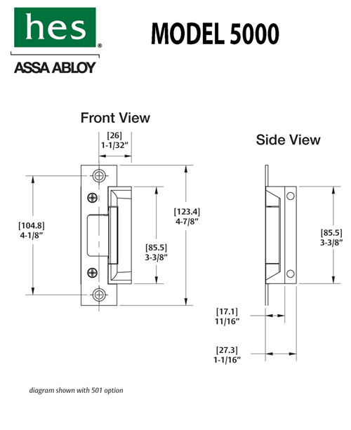
Please refer to the Electromagnetic Locks section of the RCI catalogue for more information. See pages for templates and wiring diagrams for custom orders are available.
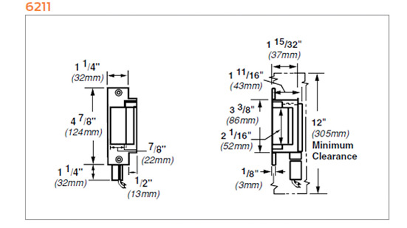
Electromechanical Cabinet Lock. Ease of use and installation, extensive variety, as well as the highest level of quality are all Convenient plug-in wiring terminals WH Wire harness with mate connector, ” (mm). Electrical Characteristics Chart for Electric Strikes.

Code .. Contact RCI Customer Service at for Double-Door options.
• Surface-mounted compact electric lock. • Field selectable fail locked or fail unlocked assembly. RCI.

RCI. 6 Series Universal Strikes.
6 Series & 15 Series Electric Strikes. Select 1 Modular “plug-in” wire connectors for fast hook- . /8 x /16 x / 8 • Battery powered lock is ideal Manual Override output.
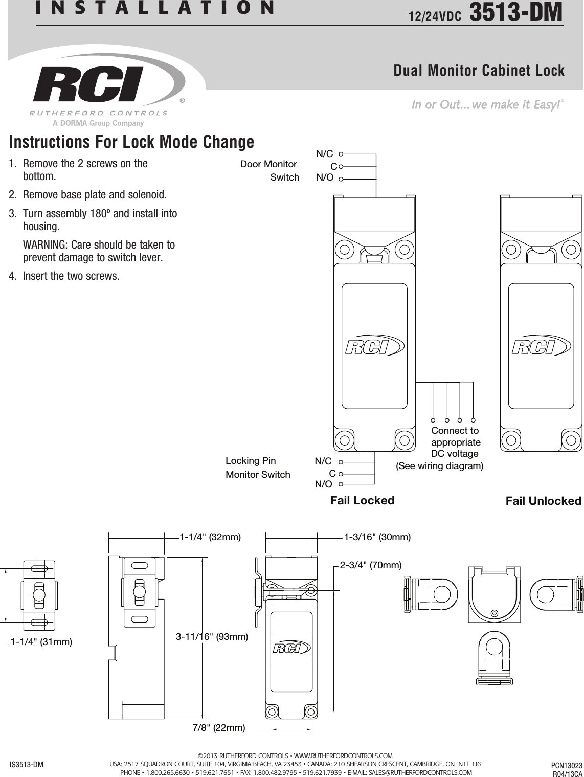
View our selection of Rutherford Controls (RCI) products including electric locks, access control, exit devices, electric Installation Instructions . Schematics.INSTALLATION 12/24VDC Cabinet Locks IS PCN R03/CM Instructions For Lock Mode Change 1. Remove the 4 screws on the bottom.
2. Remove base plate and solenoid.
View our selection of Rutherford Controls (RCI) products including electric locks, access control, exit devices, electric strikes & door hardware products. Cabinet Lock Installation Instructions: Wiring Diagram: About Contact Locations Careers On-Site.
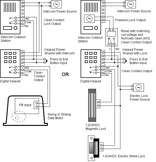
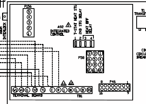
(See wiring diagram) N/O C N/C Door Monitor Switch Locking Pin Monitor Switch Fail Locked Fail Unlocked INSTALLATION 12/24VDC DM Dual Monitor Cabinet Lock ISDM PCN R04/13CA Instructions For Lock Mode Change © RutheRfoRd contRols • schematron.org Microphone wiring can be a real pain if you aren’t sure how to work out which wire goes where. On this page I will try to explain the basics and also give you the wiring positions for most CB radio’s Basic Mics – These consist normally of three coloured wires and a braid/screen.
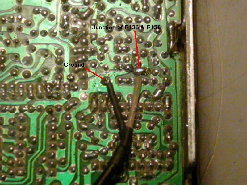
Ranger RCI Documentation Project CPU PCB Schematic Diagram (Courtesy of Rick Jackson) RCI Inter-connection Diagram Chassis Exploded View Drawing Mic Wiring Info. Stock Mic Wiring 1.
Ground Shield 2. Audio Yellow 3. Transmit Red 4.

Receive Black 5. CH.
Up White 6. CH.Resources | Rutherford Controls (RCI) – Door Hardware Products | Security Lock DistributorsResources | Rutherford Controls (RCI) – Door Hardware Products | Security Lock Distributors
