Items 1 – 12 of 57 NMEA accessories buffers and cables. Showing 1 – 12 of 57 items. Actisense Pro MUX-1 Professional NMEA Multiplexer New.
Sensor. 2. Smart Sensor.
DT-PSE. 1 Depth & Temperature.
Sensor. 3 .
interconnection diagram on page S-1 for connection. IN/OUT port FURUNO. RD SENSOR.
AUX. IN/OUT. NMEA NMEA POWER OUT.

The new, intuitive graphic remote display lets you easily view the data you need finder, autopilot, instruments and other sensors including engine information. Results – of Furuno RD33 remote display. was working fine when recently FURONO NAVNET CHART PLOTTER MODEL GDC NavNet 3D Zipper folder with installation guide.
Furuno RD NMEA Data Instrument Repeater Display Furuno Navnet Dht-Mse H/P Smart Sensor Khz. Table 5 and Figs to 14 show Furuno CAN bus connector pin functions and .
11 Fig shows the simplified circuit diagram of power supply circuit on the CAN RD NMEA Fig (b) Connection of NMEA to CAN bus network . CAN bus Instrument, FI series T-connector Smart Sensor, DST FigGPS 17x NMEA HVS Installation Instructions 6. Connect the power/data cable to the GPS 17x.
7. Route the cable away from sources of electronic interference, and connect it to power and a NMEA compliant device (page 4).
Step 2: Connect the GPS 17x to Power and a NMEA compliant device The GPS 17x NMEA HVS must be connected to. ‐‐ NMEA Pigtail 5 meter Yellow Green Blue White (not supplied) RD30 RD33 Installing the new RD33 Color display in place of your existing RD30 & NMEA Smart Sensor EXISTING RD30 DISPLAY WITH NMEA SMART SENSOR 12VDC 12VDC NEW RD33 DISPLAY WITH NMEA SMART SENSOR ‐‐ NMEA cable 6 meter (supplied)-HOW TO. Use the AUX NMEA IN grommet to connect an external NMEA sensor such as: an Airmar Smart™ Sensor, an external GPS, an external compass, or other sensor.
An “IN” device will supply additional data to the instrument/receiver/ sensor. The WeatherCaster™ software will automatically detect a Smart Sensor and display the appropriate data.
DISCUSSION WIRING AND INSTALLATION. July 15, schematron.org Installation and Operating Guideline.
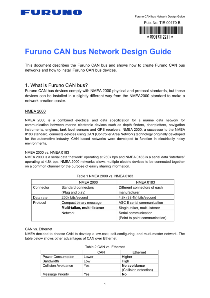
BACKGROUND. In there was a requirement to establish a Standard Data Buss for navigation and marine equipment to meet industry and IMO data messages.
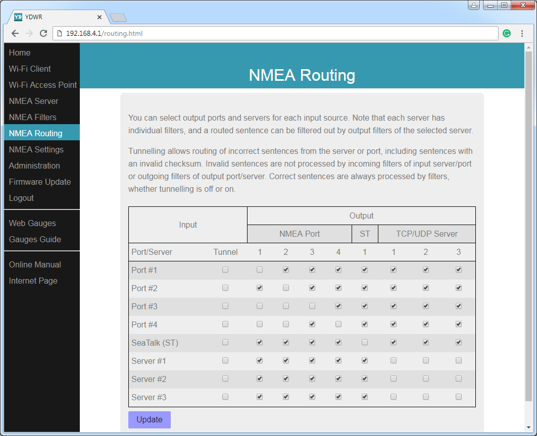
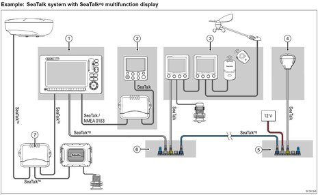
The industry was plagued with proprietary sentences and other data that was not. Diagram 6. An all-NMEA configuration with multiple NMEA listeners receiving data from the multiplexer via NMEA out.
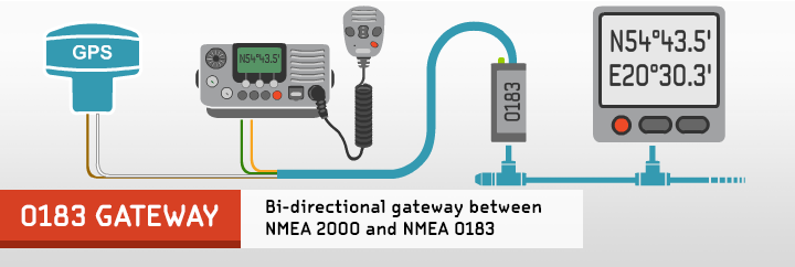
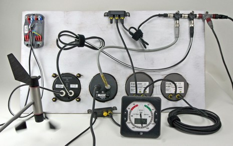
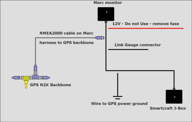
Some more examples: Standard NMEA multiplexer Diagram 1. The system shown here is a simple system with GPS and instruments from different manufacturers, all with NMEA output, no computer. The NMEA repeater can display.Furuno RD33 ” Color LCD Navigational Data OrganizerRaymarine SeaTalk Next Generation Cables and Components
