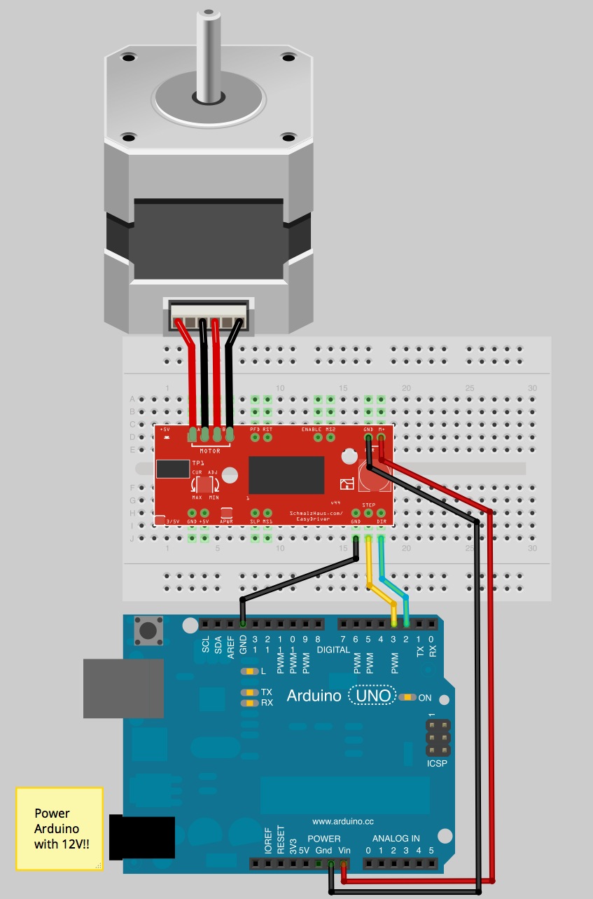
This breakout board for TI’s DRV microstepping bipolar stepper motor driver The driver has a pinout and interface that are nearly identical to those of our.
Buy Redrex mm T8x8 Lead Screw Integrated with Nema 17 Stepper Nema 17 2 Phase 4-wire Stepper Motor Degree for 3D Printer (42 x 42 x 34mm) .. The wiring diagram isn’t very clear but all you need to do is swap the inside 2. I have a stepper motor but do not have the pinouts for the motor.
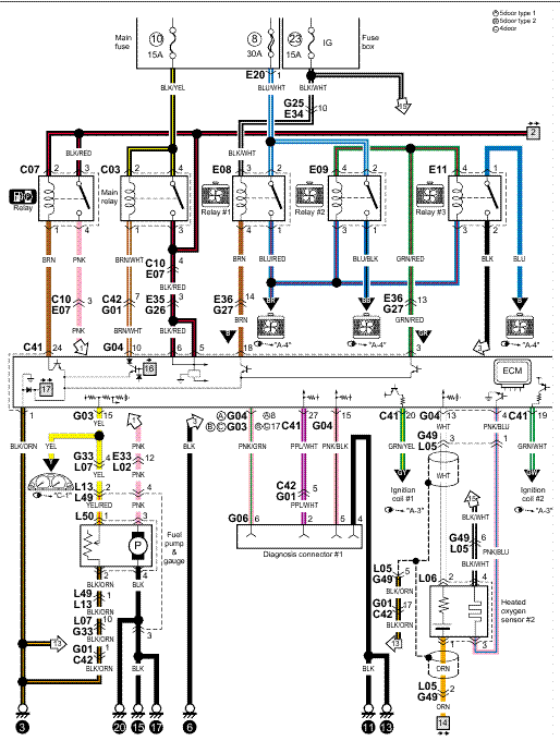
How can I determine how to wire my stepper motor without the pinouts?. I have a stepper motor but do not have the pinouts for the motor. How can I determine how to wire my stepper motor without the pinouts?. 28BYJ Stepper Motor Pinout Wiring Diagram Electronic Engineering, ..
Redrex Nema 17 Stepper Motor è stato qualificato da CECaratteristiche: * Alta.Wiring There are many variations in stepper motor wiring. For our purposes, we will focus on steppers that can be driven with commonly available drivers. These are Permanent Magnet or Hybrid steppers wired as 2-phase bipolar, or 4-phase unipolar.
Lin Engineering step motors are available with either 2-coil Bipolar, or 4-coil Unipolar windings. Bipolar motors have 4 leads, while unipolar motors have 6 leads. Additionally, some motors are designed with 8 leads, so they may be connected in a variety of ways.
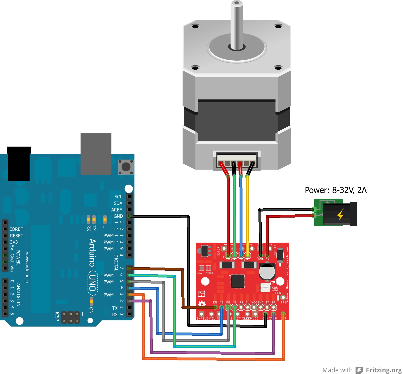
Motor Wiring Examples. The systems have been tested with an interesting mix of stepper motors, both unipolar and bipolar. All were purchased from Jameco (schematron.org).The following sections summarize some of the motors tested.
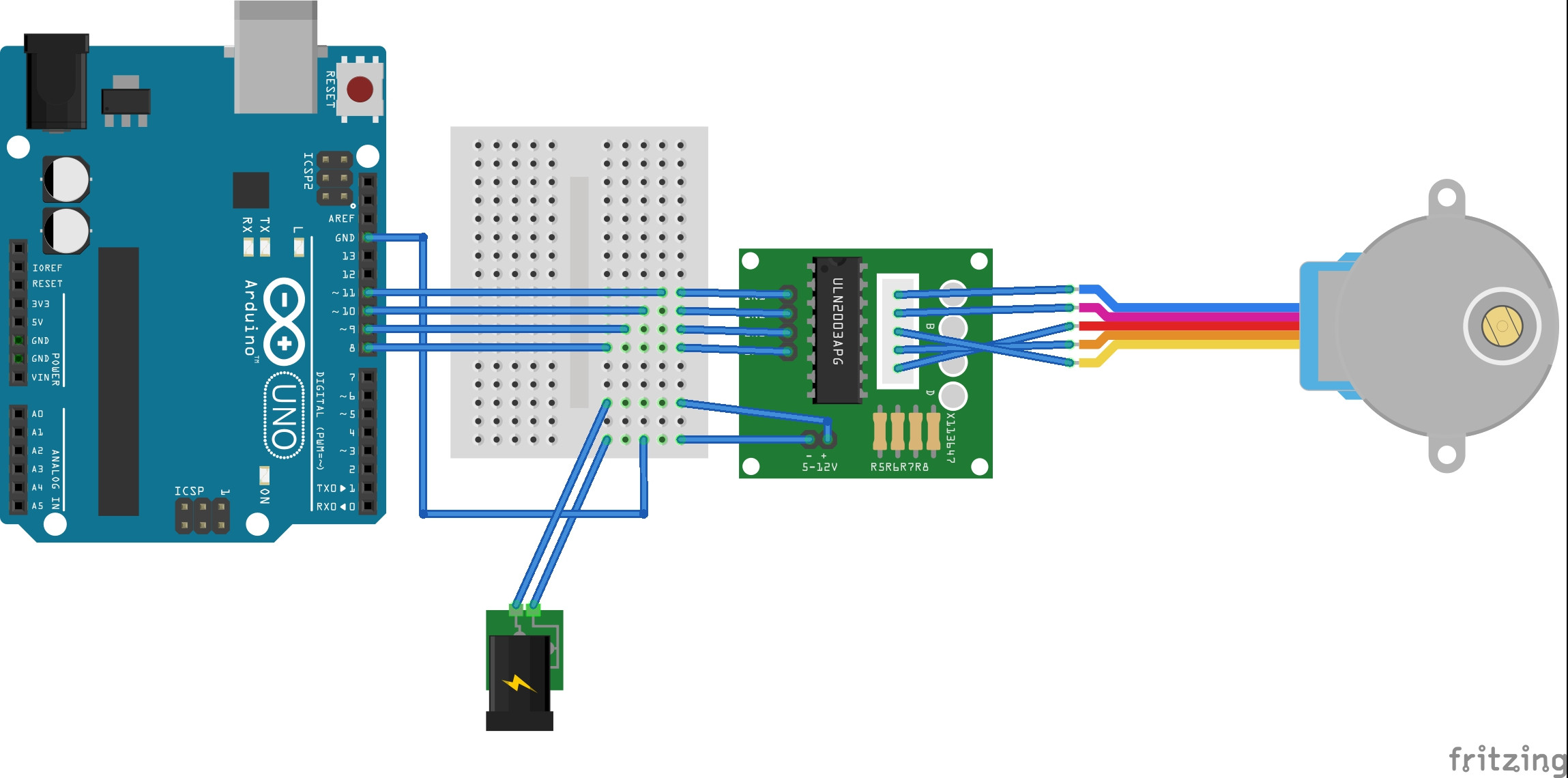
The Six Wire Stepper. We can now start to complicate things.
As it turns out, the six wire stepper is optimized to operate as a unipolar stepper motor but it is rather doable to . This wiring diagram applies to all 80VDC 7A rated stepper drives including the G, GX, G, GV, G, GX, G, GV, GM and G Please note that the GX, GX, G, and GM have onboard DIP switches for setting current, and no current set resistor is required.Answered – Robo3D R1 multiple issues | Page 2 | ROBO 3D User ForumHobbyCNC Stepper Motor Specifications
