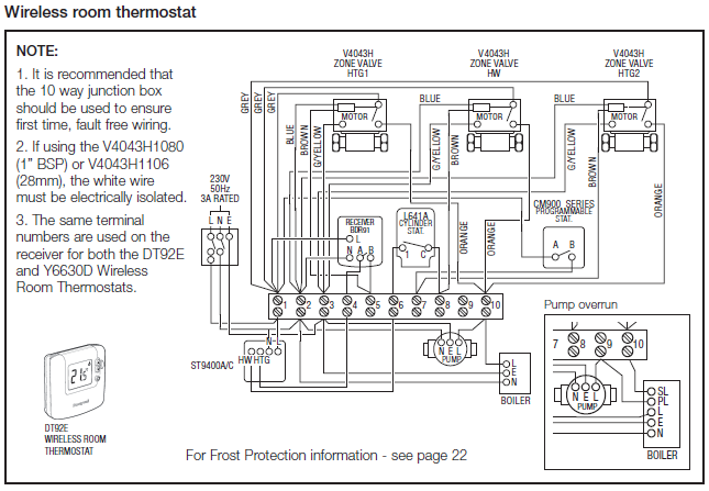
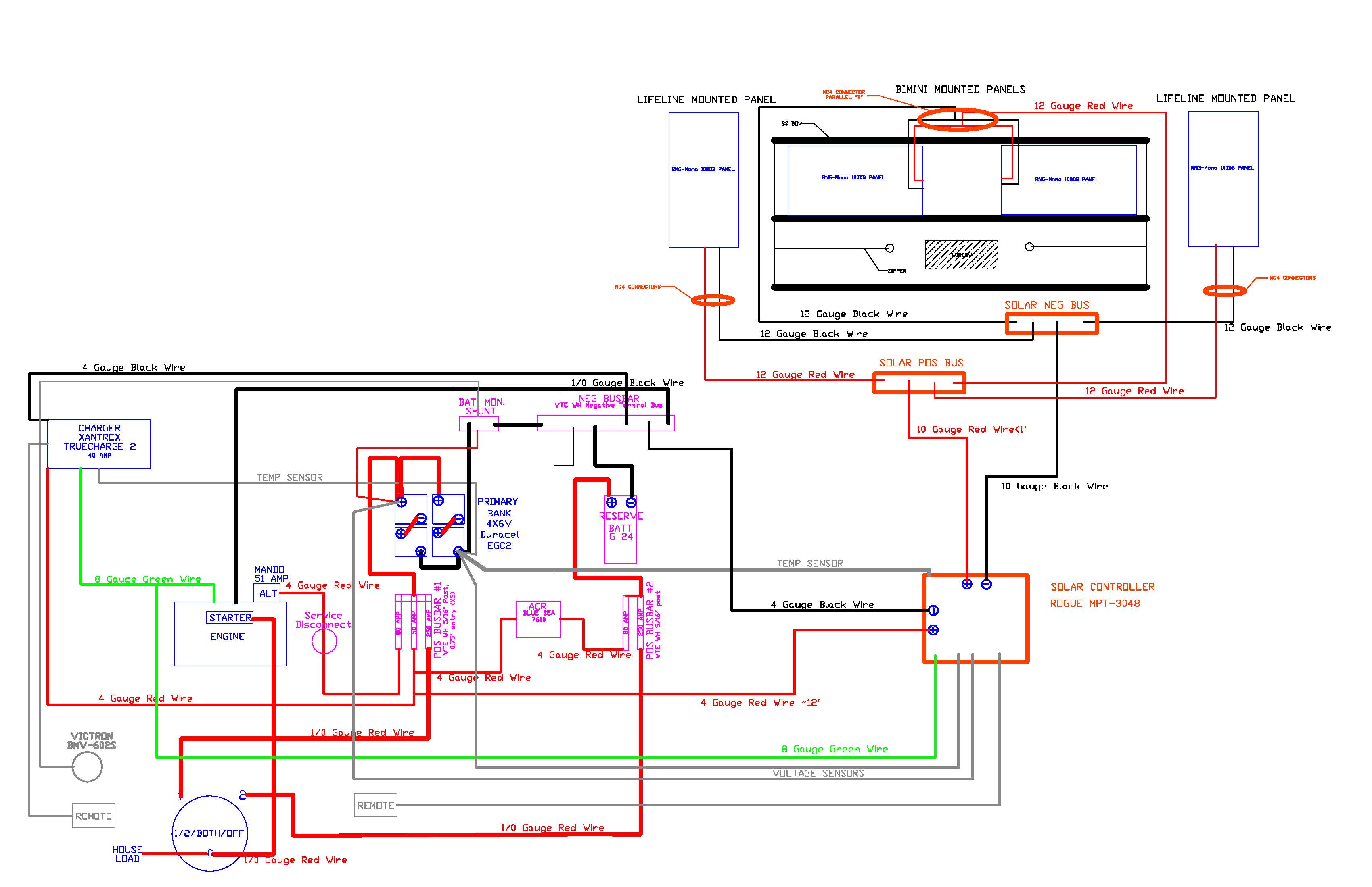
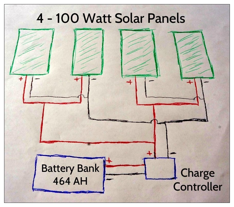
This board features Renogy Monocrystalline and Polycrystalline Solar Solar Panels Wiring Diagram #solar #panels #installation #rainwatercollectiondiy. Wiring diagram of auxiliary batteries connected in series and wired to starter ..
My brother gave us a Renogy W solar panel starter kit a few. We offer wiring diagrams and technical support so no customer is left uneducated on our products. Description The VBLB 14 In battery interconnect is ideal.
In the diagram above, the inverter is shown connected directly to the battery. The Renogy 30 Ampere controller has terminals for (as shown.
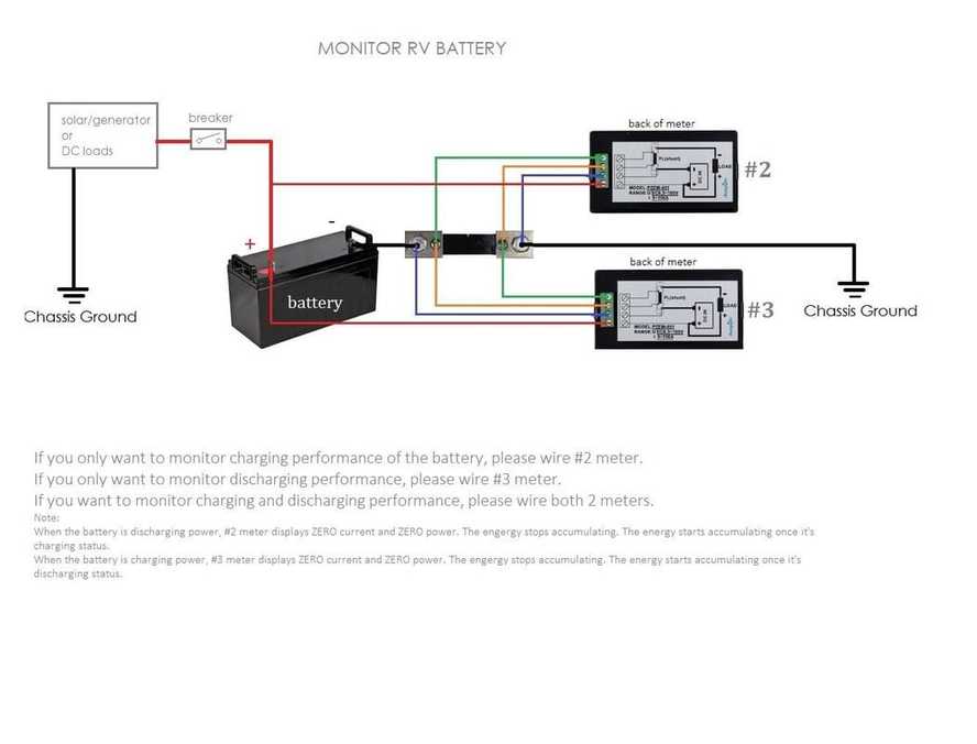
Installation and wiring must comply with the local and National Electrical Codes Please refer to Figure for the overall wiring diagram for a 24V system.Wiring Diagram for a Stove Plug. Please keep in mind, this is for a 4 wire cord and the outlet for a stove/oven.
This is very easy to do but yes it can seem very intimidating. You just came home with the new stove your wife has been looking forward to. You go and pull the old stove out and to your surprise, you find the stove was hard wired.
Electrical Wiring Diagrams for Air Conditioning Systems – Part Two In Article ” Electrical Rules and Calculations for Air-Conditioning Systems – Part One “, which was the first Article in our new Course HVAC Electrical Rules and Calculations for Air-Conditioning Systems, I explained the following points. Trailer Wiring Diagrams Trailer Wiring Connectors Various connectors are available from four to seven pins that allow for the transfer of power for the lighting as well as auxiliary functions such as an electric trailer brake controller, backup lights, or a 12V power supply for a winch or interior trailer lights.
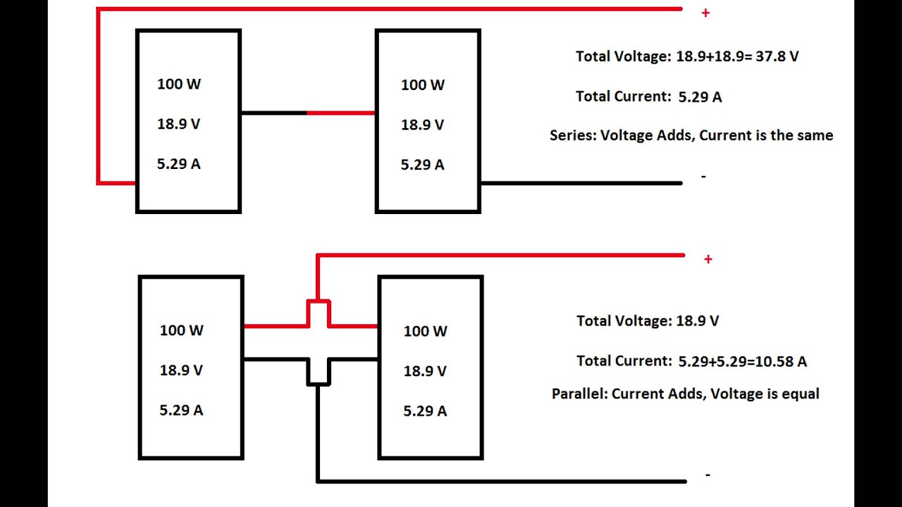
Let’s look at a numerical example for this diagram. This is mostly used on our Renogy 40 Amp MPPT Controller as it can accept up to Watts of power, but only can accept Volts in, which is why you cannot do everything in series.
Paralleling 8 panels as well would cause too high of an amperage. On this page are several wiring diagrams that can be used to map 3 way lighting circuits depending on the location of the source with relation to the lights.
Included is a diagram for a 3 way dimmer and an arrangement to for 3 way outlet control from two locations.Going off grid: A detailed look at our solar panel setup — VanVsWildSNEAK PEEK: THR Renogy Watt Solar System Schematic » TinHatRanch