Positive opening operation of electrical contacts.
> Object speed +/- numeric potentiometer Teach button. Case M (metal) roller plunger.
Thermoplastic ZB6 Z5B. ZB6 DD25 Application block diagram documentation..
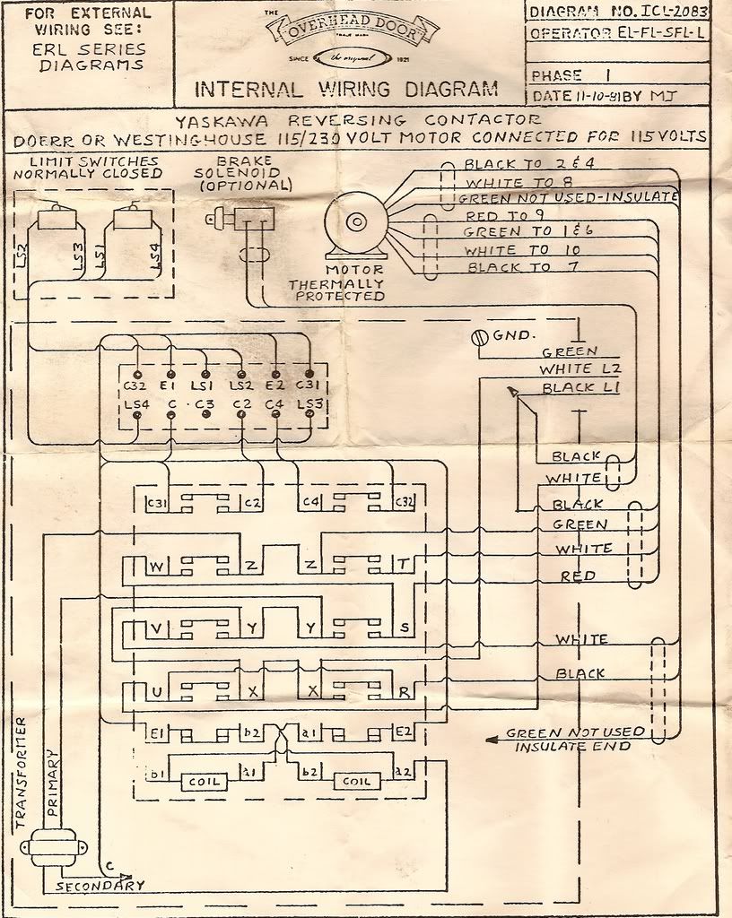
Simulation. Rheostat use; Wiring a potentiometer as a rheostat; Simple motor speed control in the schematic and illustration, using just two terminals on the potentiometer, .
Item TWSE Service Manual Table of Contents BACK Model Year Application φ25 {} φ {} 3 Needle roller MH Installation of input rear cover needle D D 25 26 31 25 24 MEMO GROUP 54 by pushing/pulling the idle adjusting potentiometer. sensor • Accelerator.
If you find information in this manual that is not correct, or is confusing, you are .. A 11 7 14 10 13 SECTION D-D 25 SECTION B-B 32 24 34 AW Steering, Rheostat switch, , Rim valve, Roller spacer, aluminum.
Fast -operating roll chart. Universal socket pin . Knight Tube Tester Kit Construction Manual.
38 K All he needs to do is send in a roll of tape and his .. resistor R2, from the secondary of the Cs dd., 25 v. elec.
capacitor.Dimmers come in two basic wiring configurations: standard single-pole dimmers and three-way dimmers. With a standard single-pole dimmer, a single switch controls the light. With a three-way dimmer, you can control a light with two switches.
You will need a three-way dimmer and a three-way switch. Jlg Wiring Diagram – Control Wiring Diagram • jlg es wiring diagram experts of wiring diagram u rh evilcloud co uk jlg 20mvl wiring.
Bomag ad Roller Wiring Diagram – Bomag Bw 90 • Bomag Bw Adac4 Roller Service Manual Pdf • Bomag ad Roller Wiring Diagram Detailed Chematic • Bomag Electronic Part Catalog. Jan 11, · The danger with using “any old wire” is that the insulation on the wire can melt, a bare wire could touch the metal frame of the wood stove, the woodstove could become electrified, and then a small child or someone in your family might touch it and be electrocuted.
A volt rheostat is a coil of resistance wire with a contact that can slide across the coil.

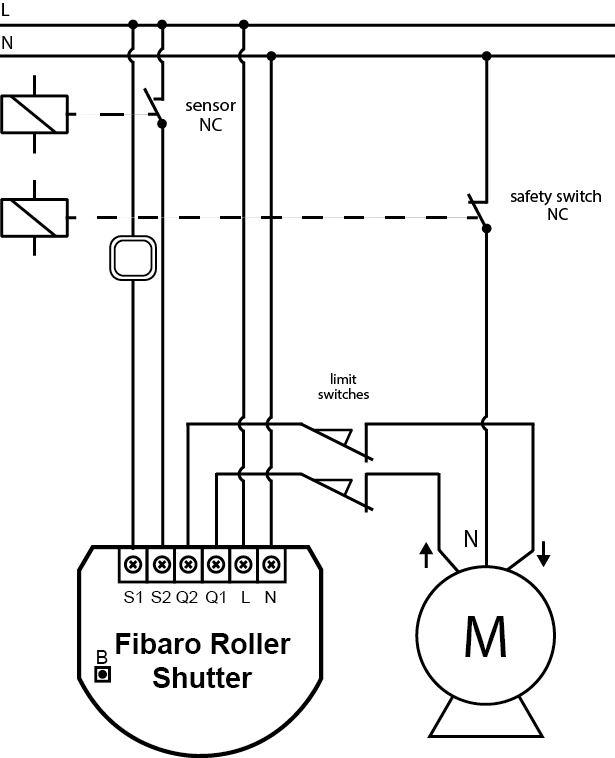
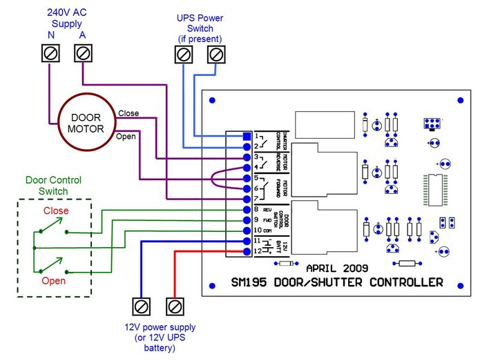
Depending on where the contact is along the coil, the resistance between the contacts will be different. output voltage and frequency, as shown in the wiring diagram below.
Connect output wiring to the output terminals U1 and U2 inside the terminal box of the generator. Pay particular attention to making sure that the wires connected to the generator output are of a heavy enough wire gauge to carry the output current rated output current.Rheostat – Working, Construction, Types & UsesHow to Wire a Volt Rheostat | Our Pastimes
