Contents. Thank you for choosing a RideTech air suspension control system.
The valve is held closed with the pressure in the tank. valve Block Harness.
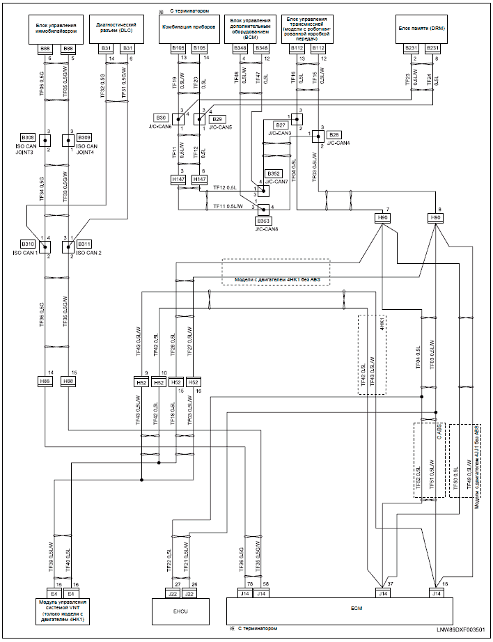
installing ARV Big Red valves need wiring diagram got 2 via air compressors, having problems just want to go with a simple front and. Refer to the factory service manual for Installing one side at a time will make the installation easier. 3.
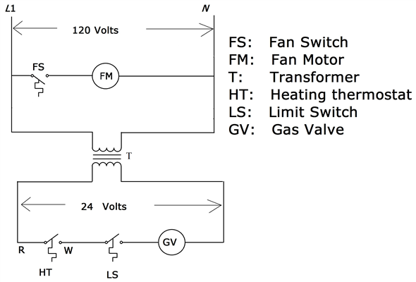
Wiring harness – Control panel to valve. 3. RideTech Air Valve Block RidePro 4-Way W/ 1/4″ NPT Ports.
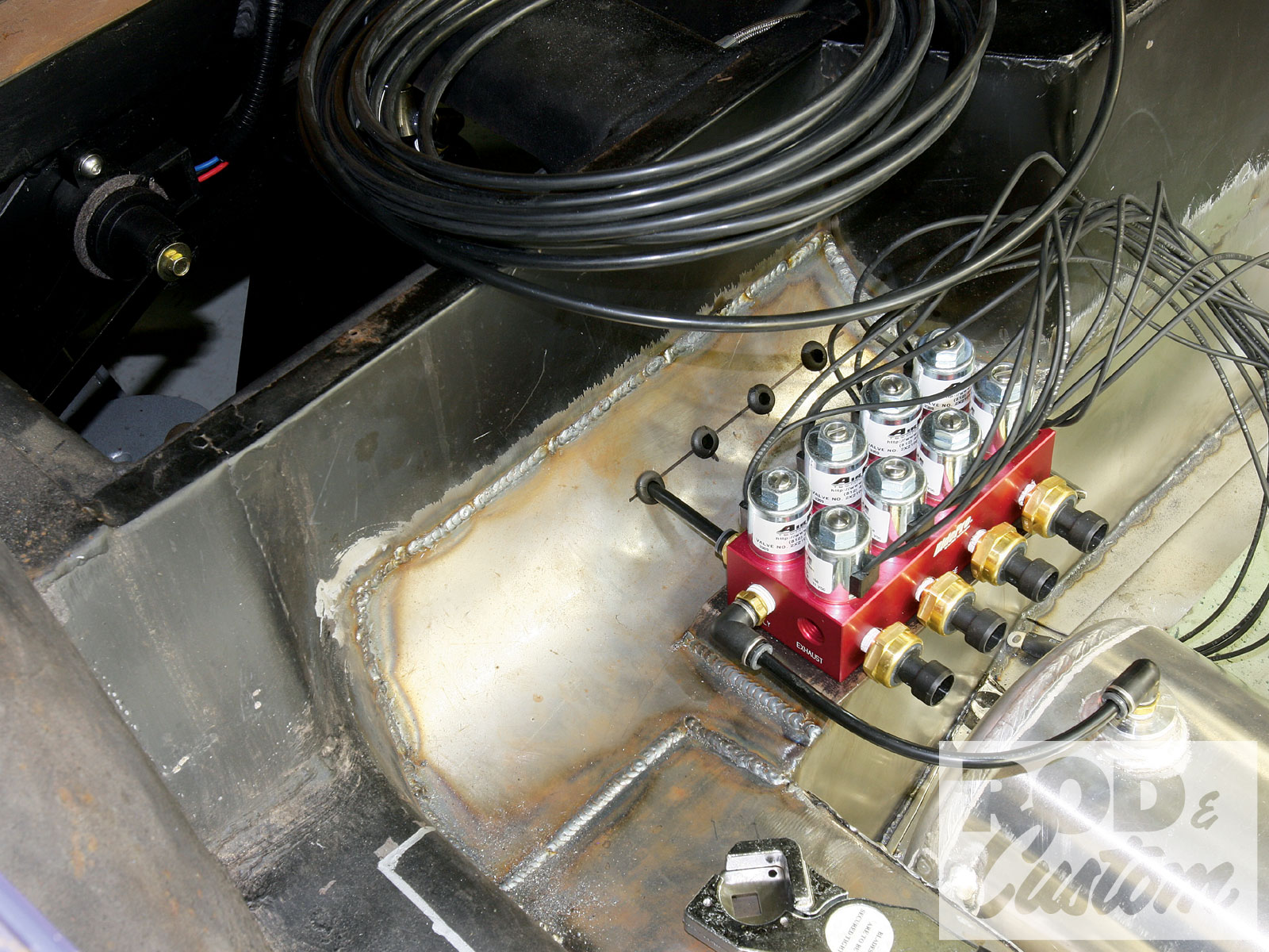
$ RideTech 10 Ft. Harness, Electric Rocker Switches.
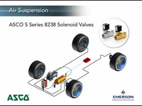
$ I have a CON switch panel and I need a wiring diagram for the switches. if Spade B Ground (Not used, will receive ground at the valve).ridetech air valve wiring diagram. schematron.org Performance Suspension Specialist.
Ridetech manufactures exciting suspension systems that improve the handling and ride quality of your muscle car, truck, Corvette or hot rod. Ridetech Wiring Diagram – in addition ridetech 4 link rear suspension moreover 69 chevelle fuse box picture moreover 12 volt solenoid wiring diagram as well as ford racing parts catalog html also ford thunderbird wiring diagram also drag race car wiring diagram further wiring diagrams for mustang moreover c10 wiring harness.
Installation and operating instructions Index LCD Controller and Relay Control Box Layouts Wire according to diagram on page 1. schematron.org Loom i. Connect the Black wires (Pin 1 & Pin 3) to (-) Ground.
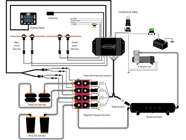
Connect each wire to its corresponding valve as shown on the Non-PnP Wiring Schematic. Wiring the compressor, ECU, and valve block was as easy as following the directions and wiring diagram, as each has a separate harness. If you’re doing likewise, just ensure grommets are used.RideTech Air Valve Block RidePro 2-Way W/ 1/4″ NPT PortsIndex of /schematron.org
