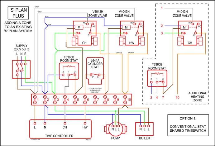
Starter Kill – Normally Open Relay Wiring Diagram. This normally open starter kill relay application below relies on a ground from the alarm when disarmed and. automate this power to switch electrical circuits on and off at particular times.
12V DC relay switches are the best solution for full voltage applications, as they. automate this power to switch electrical circuits on and off at particular times.
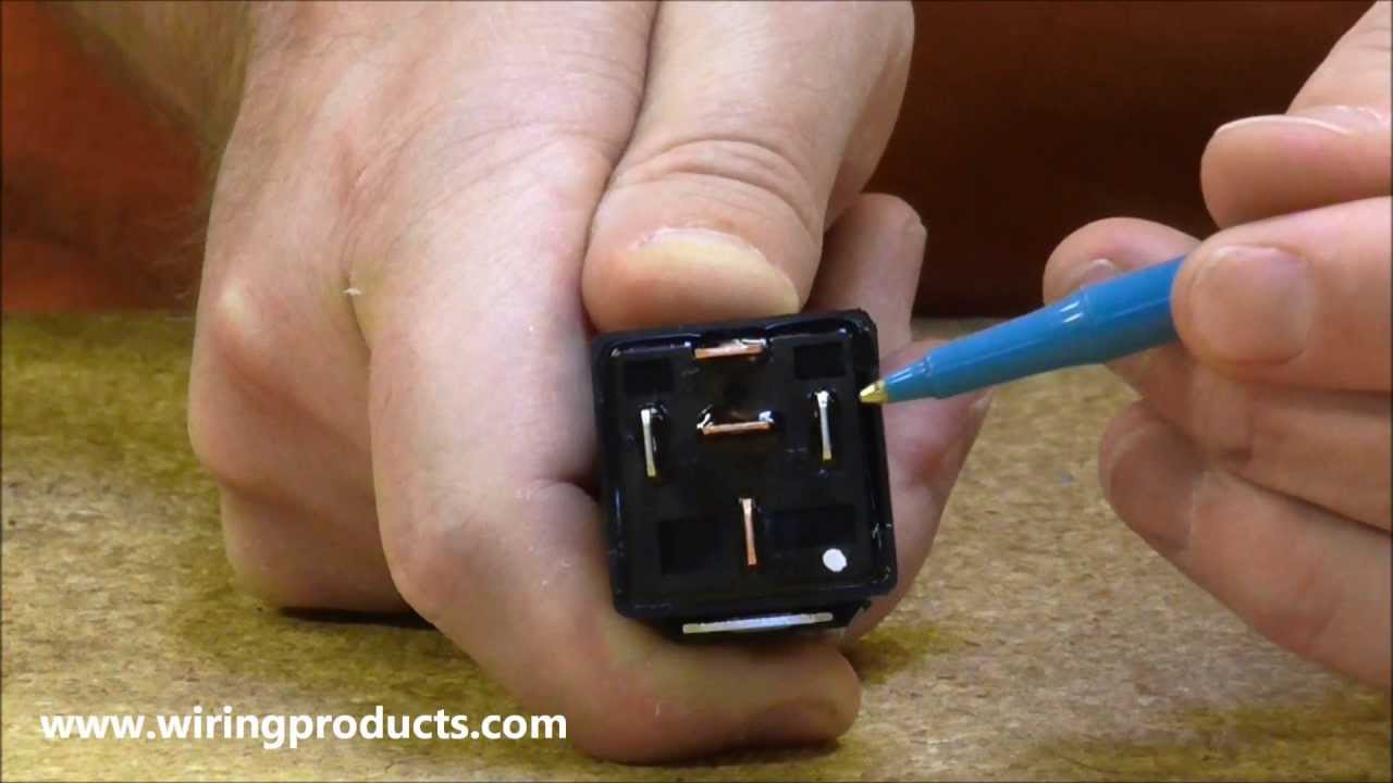
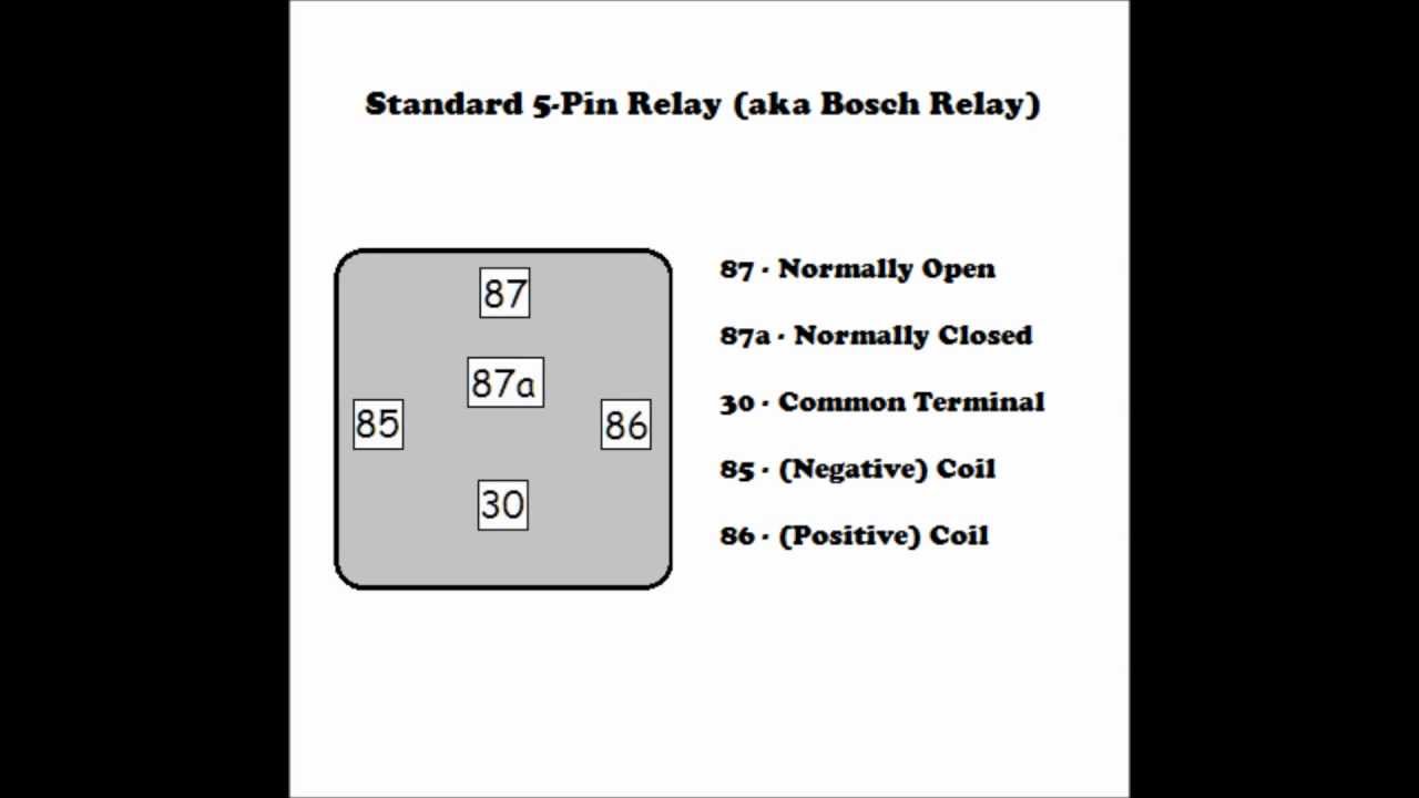
12V DC relay switches are the best solution for full voltage applications, as they. 12V Relay Common Uses with Wiring Diagrams This Bosch type 12V, 40A 5- pin relay is popular in automotive sound and security installations.
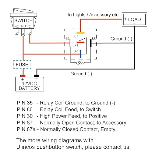
In Stock. Relay Wiring Diagrams.
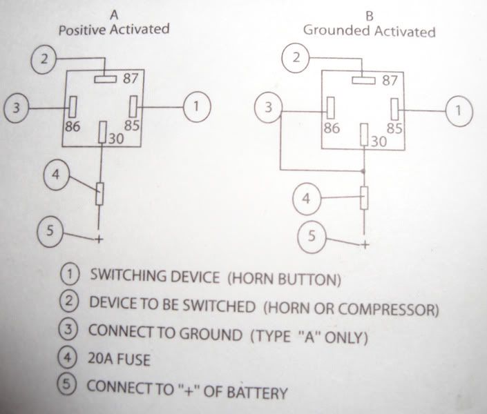
Wiring Diagrams for Single Pole Single Throw (SPST) Relays, Single Pole Double Throw (SPDT) Relays, Double Pole Double Throw.Relay Diagrams, Special Applications: • Basic Remote Start Relay Diagram • Connecting Additional Devices to Remote Turn On Wire • Constant to Momentary Output • Latched On/Off Output Using a Single Momentary Pulse • Momentary to Constant Output • One Channel to Multiple Outputs •. If the diagram you’re looking for isn’t in the list, please contact us to see if it’s a diagram we can supply.
Diagrams are mailed separately from wiring kits and are sent USPS 3 Day First Class. 11″ x 17″ are shipped in flat envelope.
18″ X 24″ are shipped in a tube. Rls Relay Wiring Diagram have an image from the other.
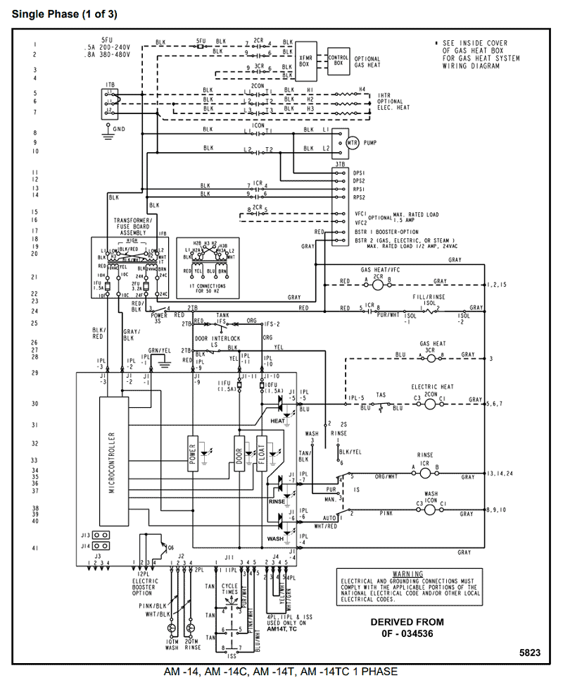
Rls Relay Wiring Diagram In addition, it will feature a picture of a kind that may be seen in the gallery of Rls Relay Wiring Diagram. The collection that. Relay Wiring Diagrams. Various Relay Wiring Diagrams.
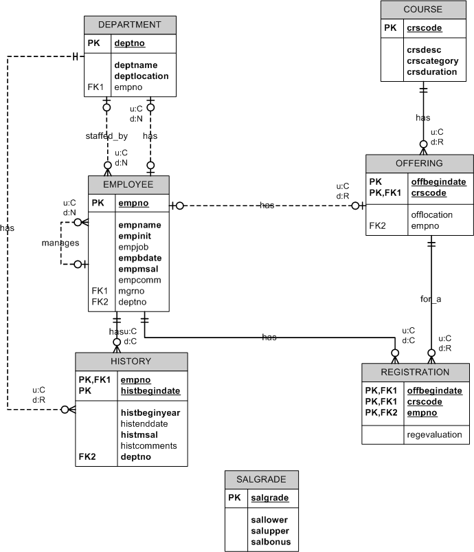
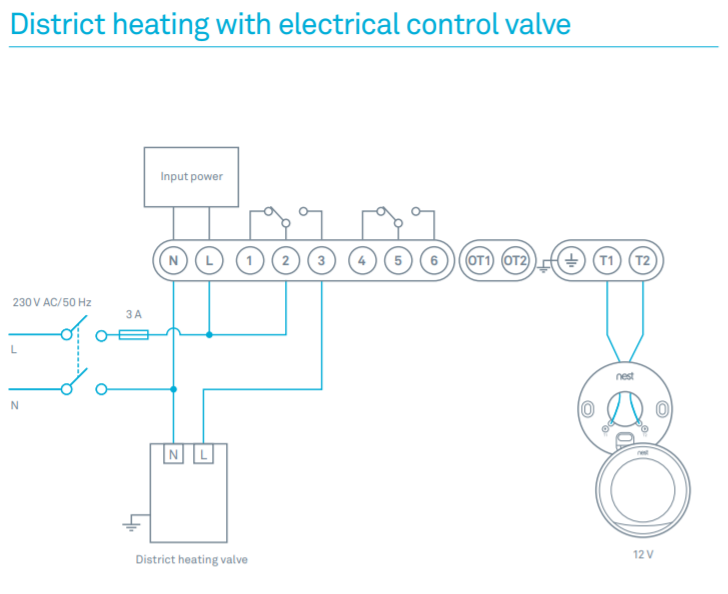
Below are the diagrams for connecting the various types of relays. Relay Wiring Diagrams.
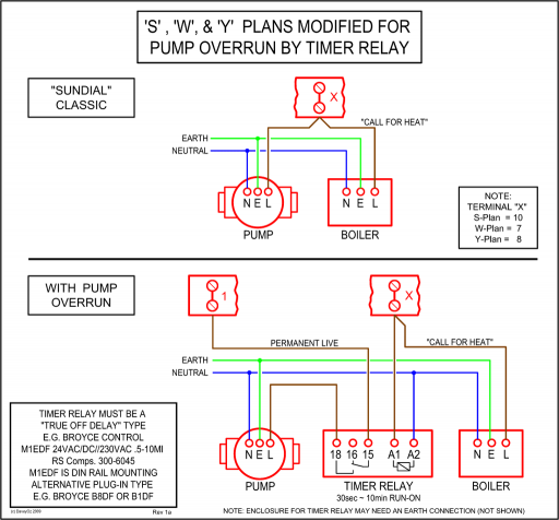
Various Relay Wiring Diagrams. Below are the diagrams for connecting the various types of relays.
This list covers Single Pole Single Throw (SPST) Relays, Single Pole Double Throw (SPDT) relays, and Double Pole Double Throw (DPDT) relays. So, I ran the hot wire to the relay, and the grounding wire from the wheel to the terminal on the relay that activates the internal switch to close.
The same hot wire runs to one terminal of the normally open switch of the relay, and the other terminal is connected the hot terminals of the horns/5().Connecting Additional Devices to the Remote Turn On Wire Relay Wiring DiagramWiring Diagram Book | Schneider Electric