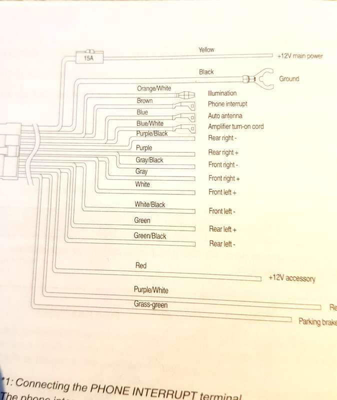
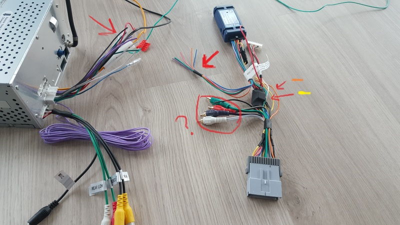
You mean you didn’t connect the orange wire (from the unit) to anything? a wiring harness adapter and not just cutting up your car’s wires.
Pioneer Harness. Pin.
Colour. Action.
How to keep your factory backup camera, OnStar, steering wheel controls, and Bose in your GM vehicl
Pin. Colour.
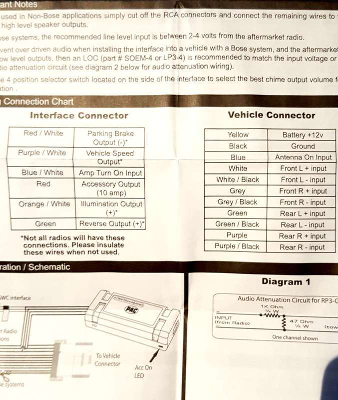
PAC RP3-GM Pin Orange. Dimmer (NOT Required on C6).
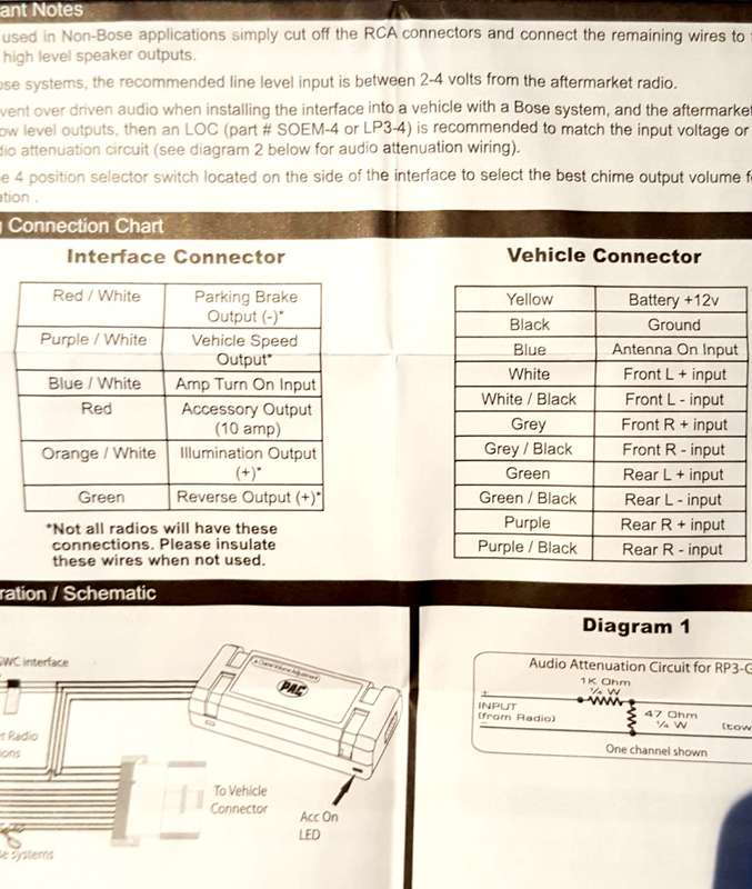
Front/Rear Output/Audio Input. Red/ White.
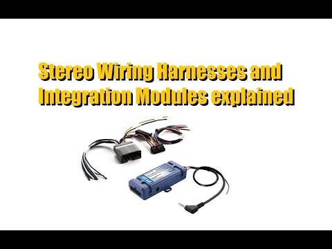
These products include both the wiring harness and interface module as a complete, all-in-one solution designed for replacing the stock radio with an. Part Number: RP3-GM Condition: Radio Replacement Interface for GM Vehicles with Class II databus and pin harness. High current.
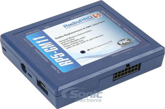
FREE 2-day Shipping: Keep your factory features PAC’s RadioPRO5 RP5-GM11 wiring interface enables you to install a new car stereo and retain useful.PAC RadioPro RP4-GM11 • PAC RP4-GM11 Reviews › PAC RP4-GM11 vs PAC RadioPro RP5-GM11 › PAC All Wiring Harnesses › PAC RP4-GM11 vs PAC RadioPro RP3-GM11 Wiring Diagram Legend. Warning: The image depicted shows the resistance change when wiring multiple subwoofer terminals.
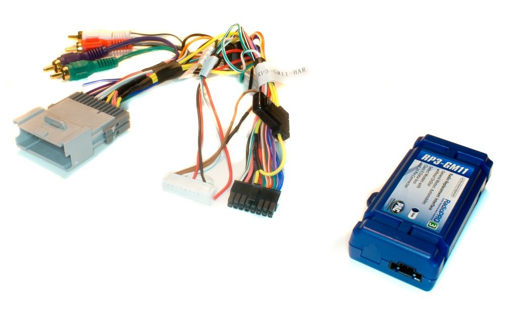
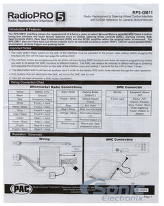
Please refer to your subwoofer’s owner’s manual for the. Wiring Connection Chart Illustration / Schematic The RP3-GM13 interface allows the replacement of a factory radio in select General Motors vehicles with Class II radios. Using this interface will retain factory features such as Warning Chimes and the BOSE amplifi er . With the RP3-GM11 you can quickly replace the factory GM Class II Radio and retain all safety features.

The PR3-GM11(formerly C2R-GM24) Version plug-n-play Chime and Data-bus Integration Interface will allow replacing the GM Class-II Radio with an aftermarket radio in select Models listed in the drop-down menu below without OnStar® or when OnStar is not serviced or unwanted. WIRING DIAGRAM BY MODEL This document describes car models to which the AFC neo (Product code: A) is applicable, and ECU terminal arrangement drawings.
For the operating method and precautions for the AFC neo, refer to the Instruction Manual. When installing the AFC neo, both this document and the Instruction Manual are required.
RJ Plug Wiring. The RJ connector has six terminals on it.

Typically, only the middle 4 are used. Line 1 is the center pair, red and green.Installation Question Where does the orange wire go? – Third Generation F-Body Message BoardsTelephone RJ11 Wiring Reference – Free Knowledge Base- The DUCK Project: information for everyone
