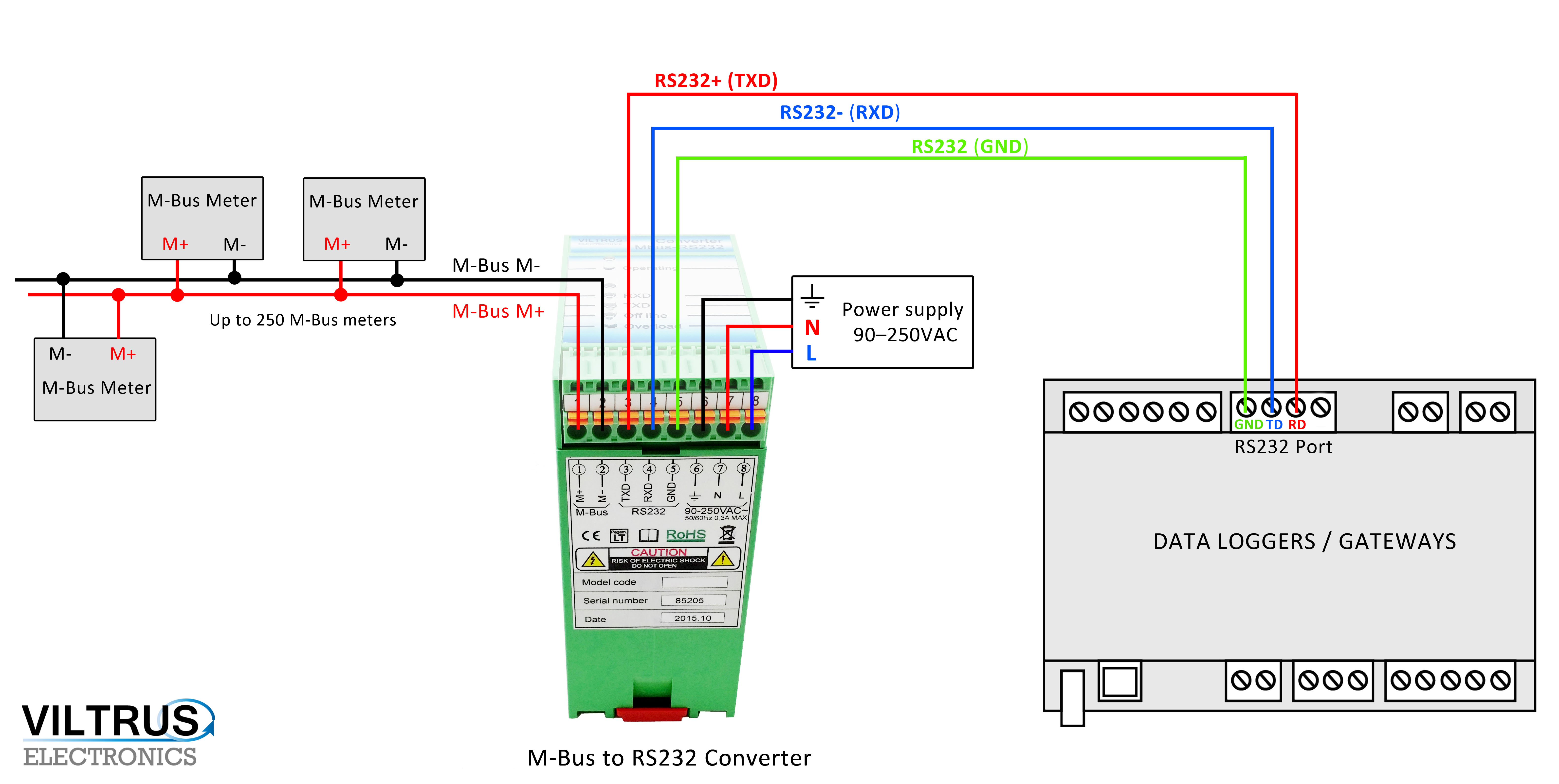
This document serves as a guide to wiring RS controllers in RS MS/TP The following diagram shows the daisy chain topology.
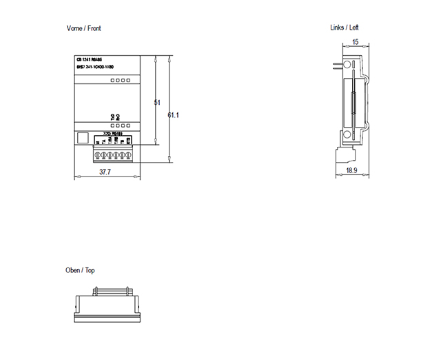
Fig. The purpose of this resolution is to diagram the RS wiring for Modbus communications between a Momentum processor and a Merlin Gerin DC Read this manual thoroughly before using the RS communication function.
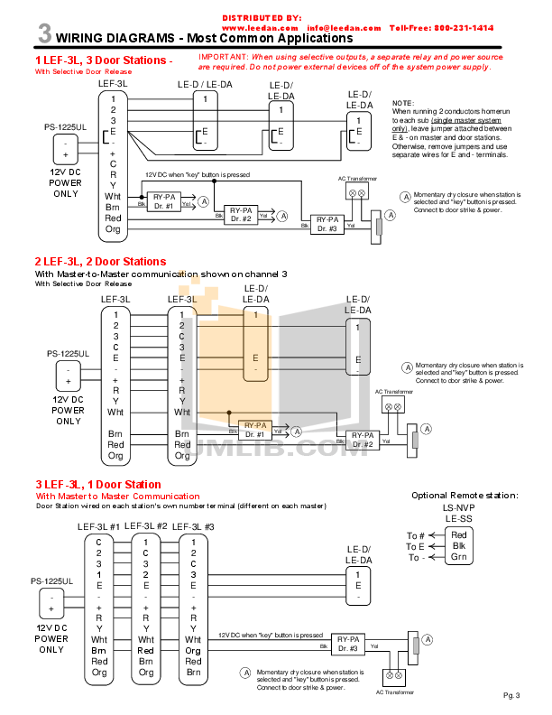
communication cables are broken, the followers continue running based on. A description of proper wiring methods for RS networks with attention to cable type, The diagrams below are examples of improperly configured systems. First check the pinout connections and specifications of the devices you want to connect in order to determine whether you need a “2-wire” RS connection or .RS, also known as TIA(-A), EIA, is a standard defining the electrical characteristics of drivers and receivers for use in serial communications systems.
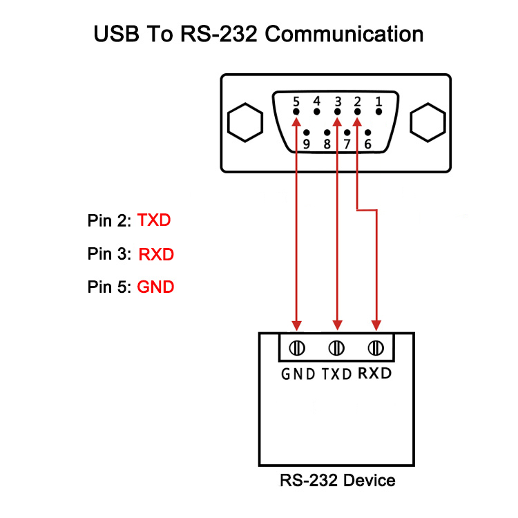
Electrical signaling is balanced, and multipoint systems are supported. AN Wiring Guidelines for RS networks _____ Grounding Grounding is essential to reliable operation of any RS network. EIA is a three-wire system.
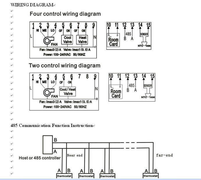
The third wire is required so that all nodes on the bus, share a common ground reference connection. This ground wire could be a separate wire or a pair of the twisted pair cable.
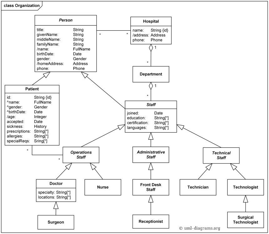
Two switches are set for 2W or to the 2-Wire RS Mode. Figure 3 applies to most B&B RS Converters or Serial Cards that can be set for 2-wire or 4-wire operation, and for some 2-wire Converters that use the same circuit board for the RS model.
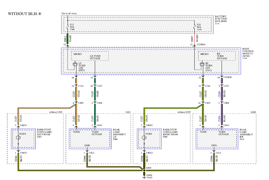
Check the Data Sheet schematic or block diagram. The basics of the RS standard.
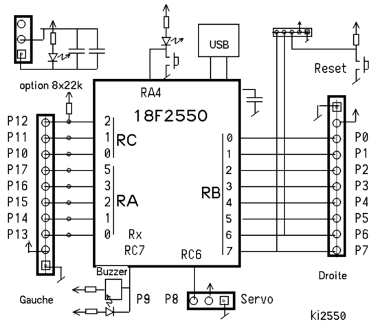
Read our white paper for information that touches on the most commonly asked aspects of RS cable wiring and protocol. To ensure proper RS communication, terminating resistors are used at both ends of a bus to reduce voltage reflections.
To apply this to a VC network, the FIRST and LAST devices on a bus.Understanding RS Wiring, Connection, Monitoring Software – Windmill SoftwareUnderstanding RS Wiring, Connection, Monitoring Software – Windmill Software