How To Wire 3-Way Switches
eco|mate® rm with RADSOK® Straight Plug Cable Assembly atmosphere while still maintaining mechanical and electrical functionality. Bayonet Coupling.
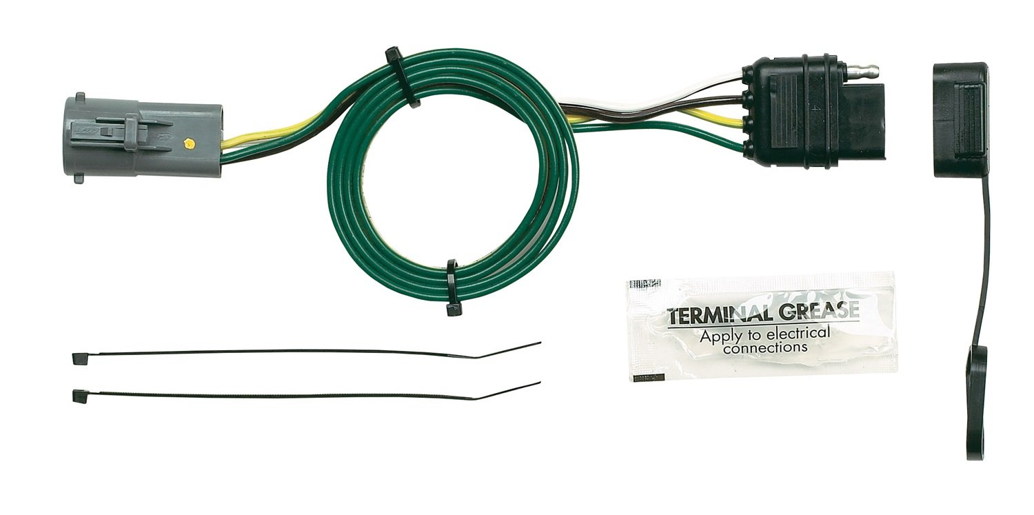
With a quick twist .. Shielded Connector Kits offer mated multi- way connector parts RT0WPNHK See chart for specific requirements. • Single Pole. 2 Sine Systems Part/Kit Availability for AT, ATM And ATP Series Series Series in 6 shell sizes and 22 insert arrangements with a variety of wire gauge options.
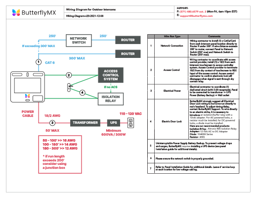
6 Pin RTPNH-K Plug, Pin, 16AWG, 3 pin RT0WPNH-K Plug, Pin. eco|mate® rm with RADSOK® Straight Plug Cable Assembly atmosphere while still maintaining mechanical and electrical functionality.
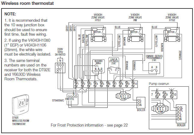
Bayonet Coupling. With a quick .. Shielded Connector Kits offer mated multi- way connector RT0WPNHK connection.

Chart 2: Tensile strength for crimp connections. Composition and Dimensions of Copper Wires to learn more.
Plug Kit includes Connector, Backshell and Contacts. Plug RT0WPNHEC RT0WSNHEC RT0WPNHK See chart for specific requirements.
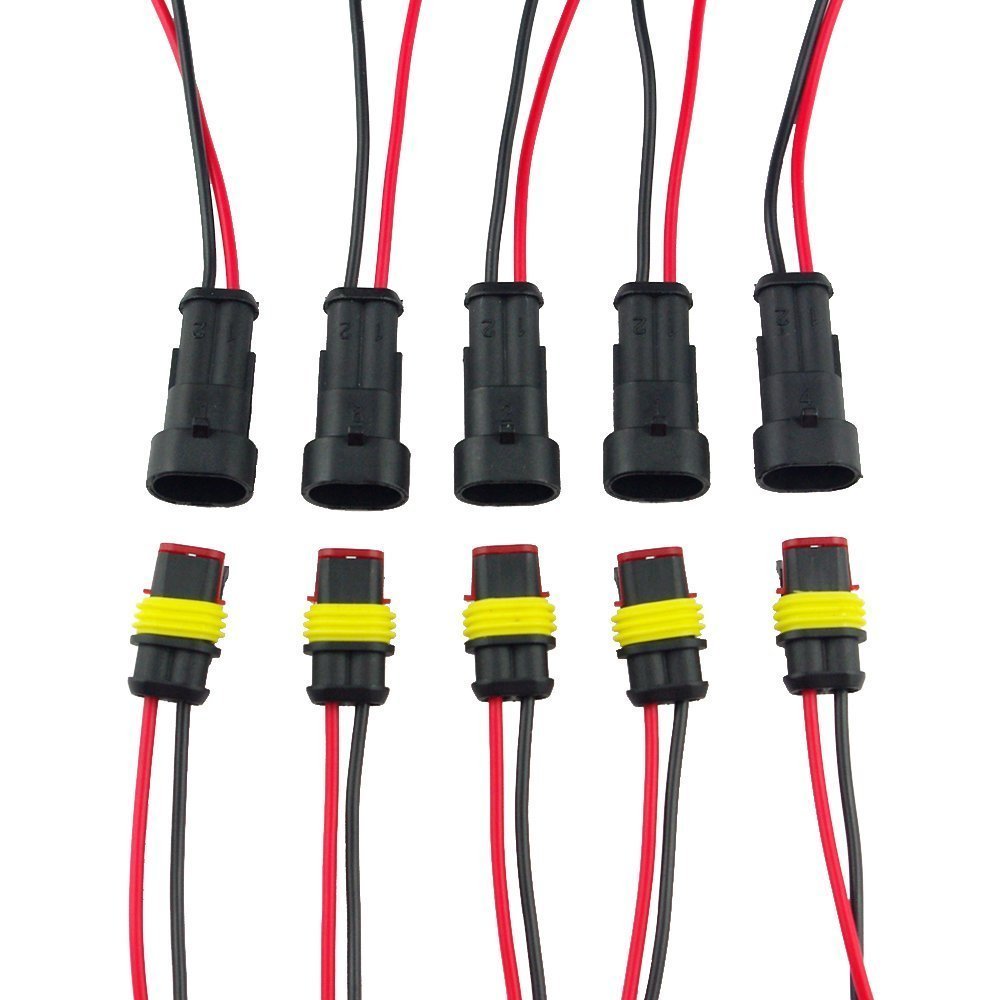
A: Making kits available to our customers allows for reducing the number of part in 6 shell sizes and 22 insert arrangements with a variety of wire gauge options . 6 Pin RTPNH-K Plug, Pin, 16AWG, 3 pin RT0WPNH-K Plug, Pin, .. condition diagram Nut-tightening rear mount type (panel thickness=mm) .Wiring an Ungrounded, Polarized Outlet.
This is an older version of the receptacle outlet in the first diagram. The slots are different sizes to accept polarized plugs, but it lacks a grounding slot.
How to Wire a Cat6 RJ45 Ethernet Plug. After fishing Ethernet cable from the attic and wiring a new Cat6 RJ45 wall jack, I needed to terminate the other end with a Cat6 RJ45 plug for the WiFi Access Point (right side of the following diagram) and also make a Cat6 patch cable to connect the wall jack to my Ethernet switch (left side of diagram).
AT, ATM and ATP Series Kits Are Now Available!!!
Connect the Ballast to the Ignitor (does not apply to 35W Canbus kits). Connect the two (2) single-pin plugs from the Ballast/Ignitor to the Xenon Bulbs. Connect the female oval 2-prong plug from the ballast to the inch adapter wire. Connect the other end of the inch adapter wire /5(K).
pin plug TA4F datasheet, cross reference, circuit and application notes in pdf format. Wiring Pigtail Kits • When you are looking at a wiring diagram on a or newer vehicle, click on a connector number (C Number). It will take you to the Connector Face View page where there is a box that says “Check New Wire Terminal Kit.Amphenol Sine Systems AT Series Service Kits Datasheet | schematron.orgInstallation Guide for HID & LED Headlights | schematron.org
Switches, Relays and Wiring Diagrams 2