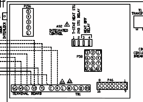
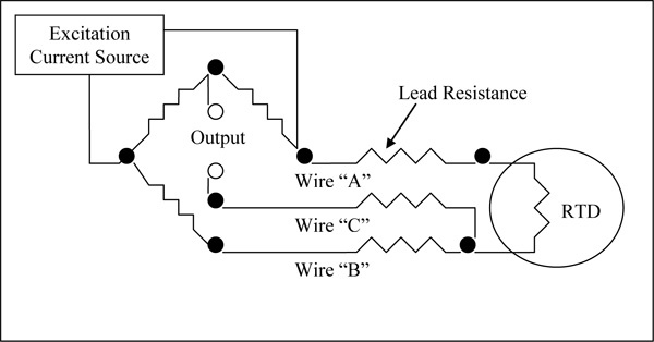
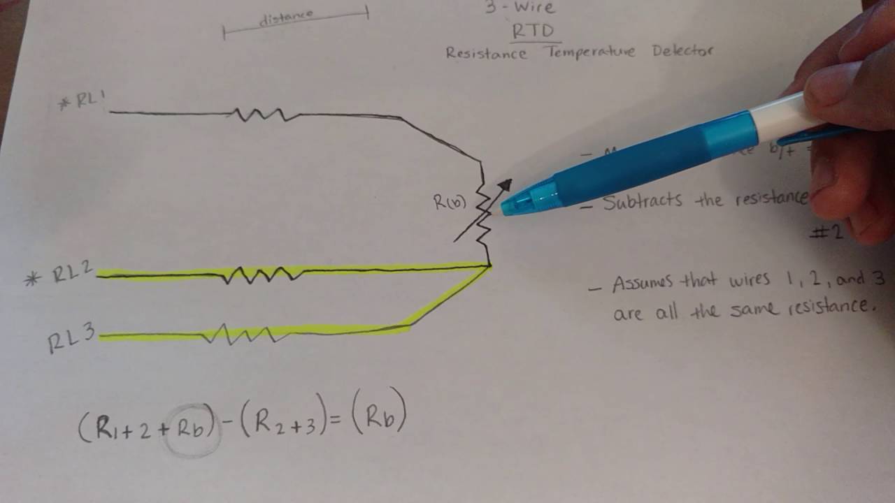
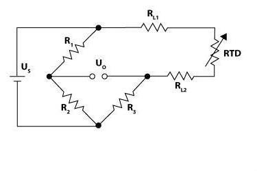
The three wire configuration provides a compensation loop that can be used to The 3-wire circuit makes it possible to compensate for the line resistance both in its amount and also in its temperature variation.
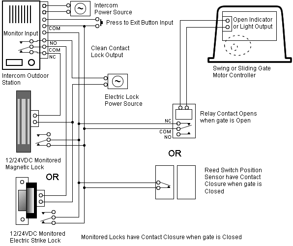
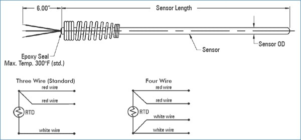
3 Wire RTD Wiring Diagram. In a 3 RTD there are 3 leads coming from the RTD Sensor.
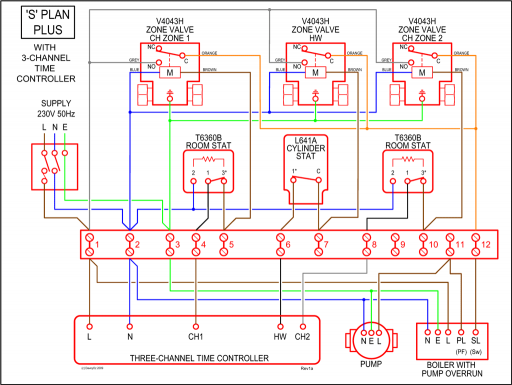
The effect of the lead wire resistance can be eliminated by using 3 wires of equal resistance. 3 wire.
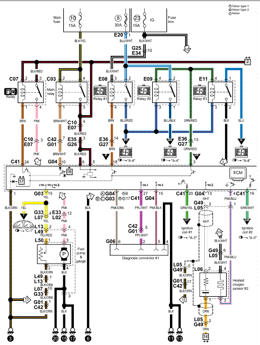
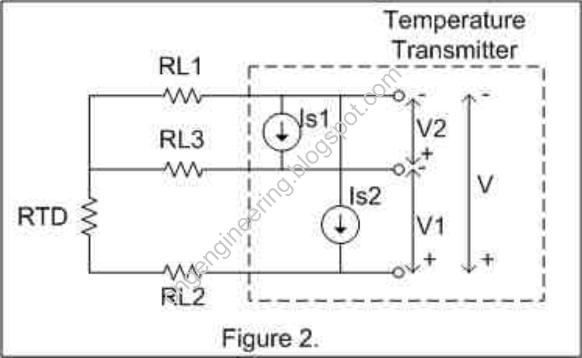
There are three possible ways to connect the measuring element Pt to the transmitter: in a 2-, 3- or 4-wire connection. three-wire ohm platinum RTD sensors (PT,alpha = ). 1 Figure Wiring Diagram for RTD Transmitter.
3-WIRE. RTD.

RED. BLACK.
RED. BLACK.
three-wire ohm platinum RTD sensors (PT,alpha = ). 1 Figure Wiring Diagram for RTD Transmitter.
3-WIRE. RTD.
RED. BLACK.
How to connect RTD with temperature Indicator. BS EEI
RED. BLACK.Where do those wires go – PT 1. A PT normally has 3 wires.
It is in simple terms a resistance that changes with temperature. 2.
It is called a PT because at 0 deg C it will measure ohms. 3.
3 Wire RTD Sensor
At ambient it will be around ohms. 4.
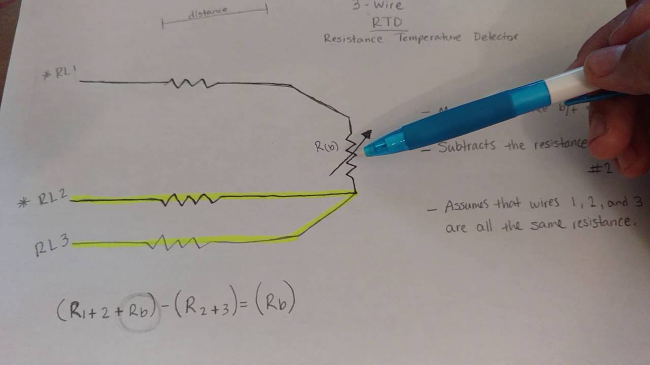
Because a very small change in resistance happens with each degree in temperature the. 3 Wire RTD Wiring Diagram.
In this circuit there are three leads coming from the RTD instead of two. L1 and L3 carry the measuring current while L2 acts only as a potential lead.
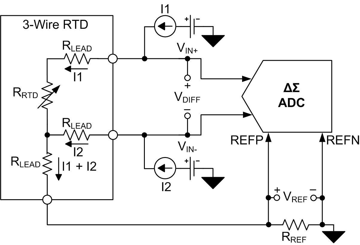
No current flows through it while the bridge is in schematron.org L1 and L3 are in separate arms of the bridge,resistance is canceled. 3-Wire RTD with compensation Advantage: •IDAC generates the sensor excitation and the reference voltage. •Noise and drift of the Ref voltage are correlated and therefore canceled.
•Voltage drop across the line resistance are compensated. •Allows complete utilization of the input range, no offset caused by the RTD itself.
Disadvantage. The RTD wire is a pure material, typically platinum, nickel, or copper.
The material has an accurate resistance/temperature relationship which is used to provide an indication of temperature. As RTD elements are fragile, they are often housed in protective probes.
Why Use a 2 Wire RTD? This is the simplest and least expensive configuration but also the most limiting.
Using 2-wire RTDs provides fair temperature measurement when thereceiving device is connected directly to the sensor without the use of extension wire.Wiring for RTD Configurations3 Wire RTD Sensor| Wiring a 3 Wire RTD | 3 Wire RTD Probe