Please help me… S8610U Damper Error Issue
View and Download Honeywell SU installation instructions manual online. SU Control Unit pdf manual download.
Replacing the Robertshaw HS 780 control with the Honeywell S8610U on the gas furnace. Part 5
With or without vent dampers. A.
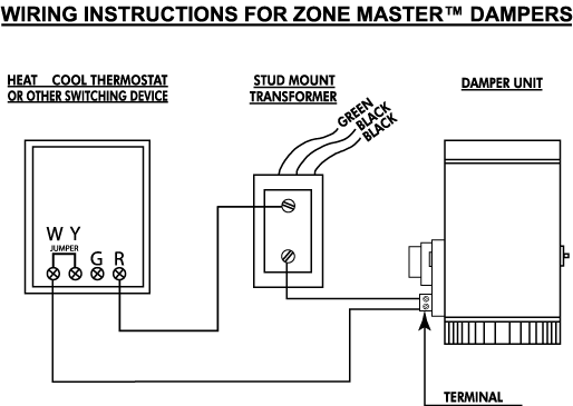
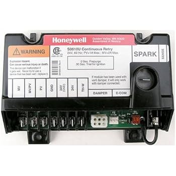
11 SU Control Layout SPARK MV TH-W (OPT.) 14 Wiring continued For systems with a vent damper connect the damper to P1 Once the vent damper. When replacing an existing ignition control with the SU, 24V.
1/4 inch. Optional—.
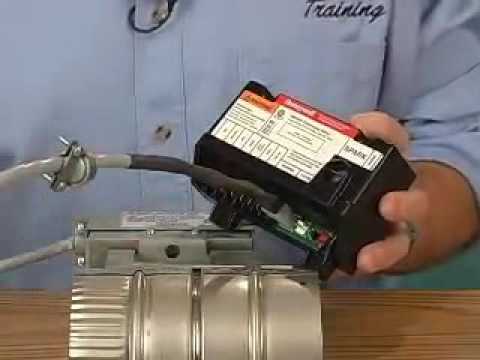
24 Vac power connection for Vent. Damper. TH-W.
1/4 inch. Connector.
Ignition Sequence. (After prepurge, if prepurge is selected).
Honeywell S8610U Installation Instructions Manual
Integral. Damper.
Connector a Use existing wiring harness to make connections to SU. Vent damper connection with automatic vent damper plug; makes for easy ..
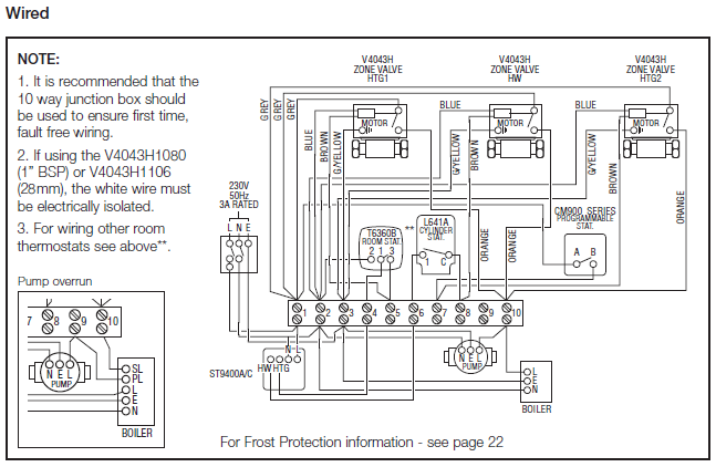
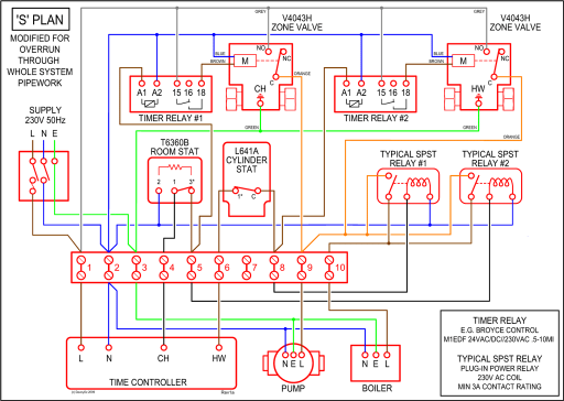
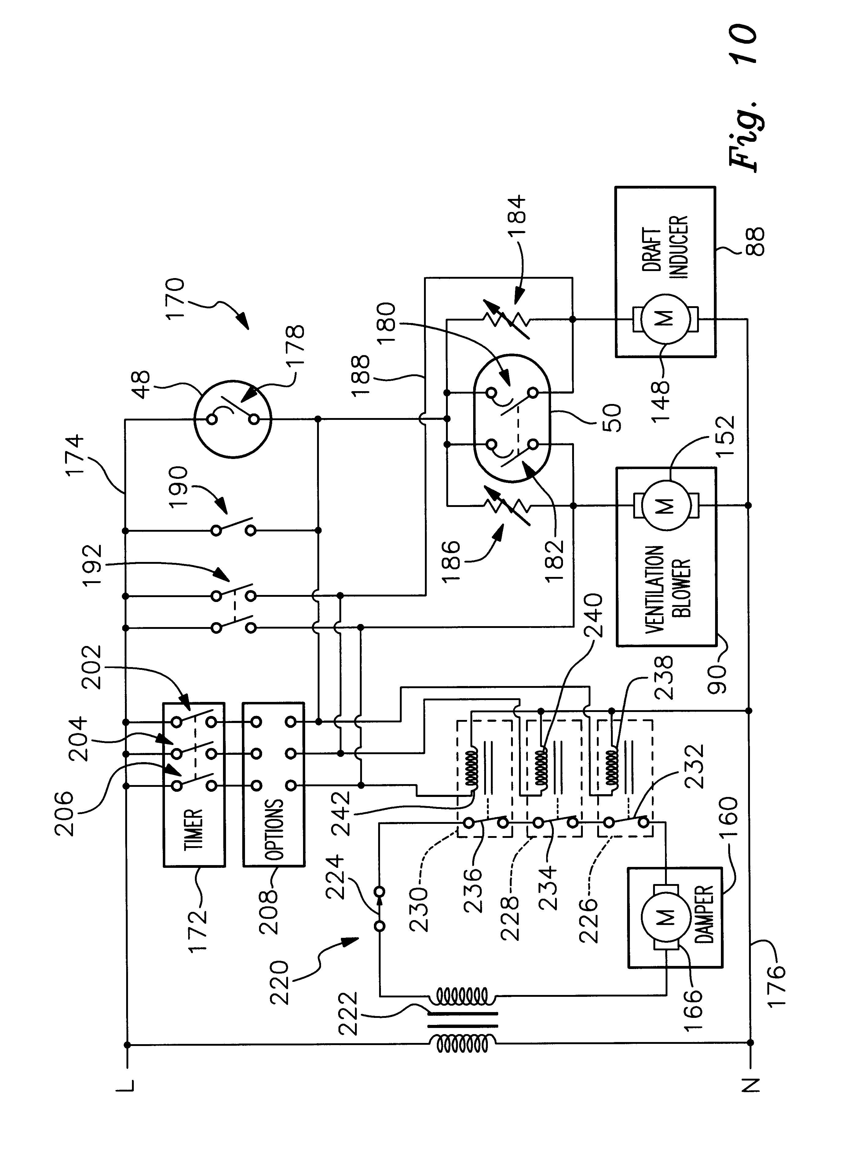
gas control terminals as shown in wiring diagrams, using terminals appropriate to .Su Wiring Diagram For Gas Control Jpg Fit Ud Honeywell Su Wiring Diagram For Gas Control Jpg By Honeywell Trol A Temp Wiring Diagram ImageResizerTool Com November 24th, – By honeywell trol a temp wiring diagram in addition honeywell lr wiring diagram along with electric d er motor as well as control wiring diagram. Connect Vent Damper The D80B Vent Damper can be used with all ignition modules, although the Molex plug provided on some mod-ules simplifies wiring connections when used with the D80D Plug-In Vent Damper.
Once a module with vent damper plug has powered a vent damper circuit, it cannot be used in a gas system without a vent damper. A non. if the vent damper is connected, wire 24v terminal, as shown.
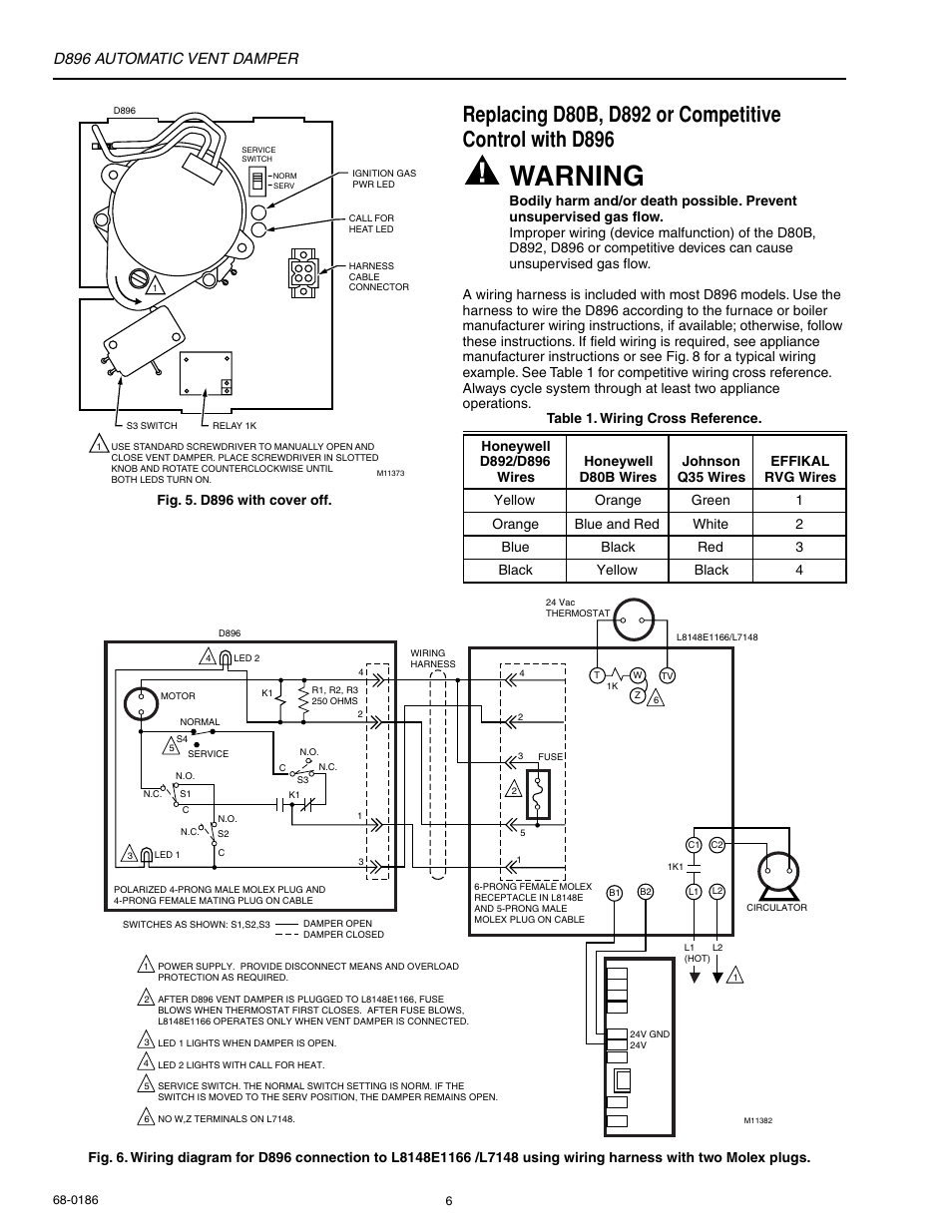
connect vent damper cable in place of plug shipped with the su. if no vent damper is connected, do not wire 24v terminal.
Honeywell S8600C Pilot Control Module
page su universal interm ittent pilo t module start stage 1 trial for ignition stage 2 main burner operation fig. 4.
su in typical st application. Table 1.
Typical wiring connections. Connector Label Size or Type Description MV 1/4 inch Main Valve connection Do not use the 24V terminal on the SU. If the old module had a vent damper, connect it to the P1 connector on the module, and wire the terminals as indicated in Table 1.
SU Universal Intermittent Pilot Module APPLICATION The SUPER TRADELINE® SU Universal Replace-ment Ignition Module is designed to provide easy field replacement of a wide range of intermittent pilot ignition modules manufactured by Honeywell, Robertshaw, Penn-Johnson and others. The SU module provides.HONEYWELL SU INSTALLATION INSTRUCTIONS MANUAL Pdf Download.Universal Intermittent Pilot Module | Industrial Controls